


Wall
Plastic
cover
Rear
panel
Wiring
5"
Wall
Wall fixture
Connector Wiring
5"
44
K
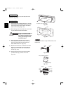
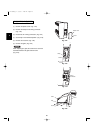
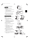
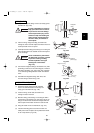
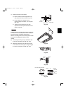
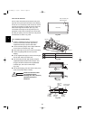
(1) Insert the inter-unit wiring (according to local
codes) into the through-the-wall PVC pipe. Run the
wiring toward the indoor side allowing approx. 5" to
extend from the wall face.
(Figs. 3-59a and 3-59b)
KHH(S)2672R
CAUTION
Never fix the wiring by any
means before the indoor unit is
fully seated on the rear panel.
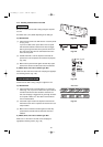
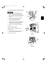
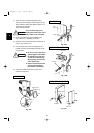
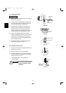
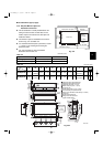
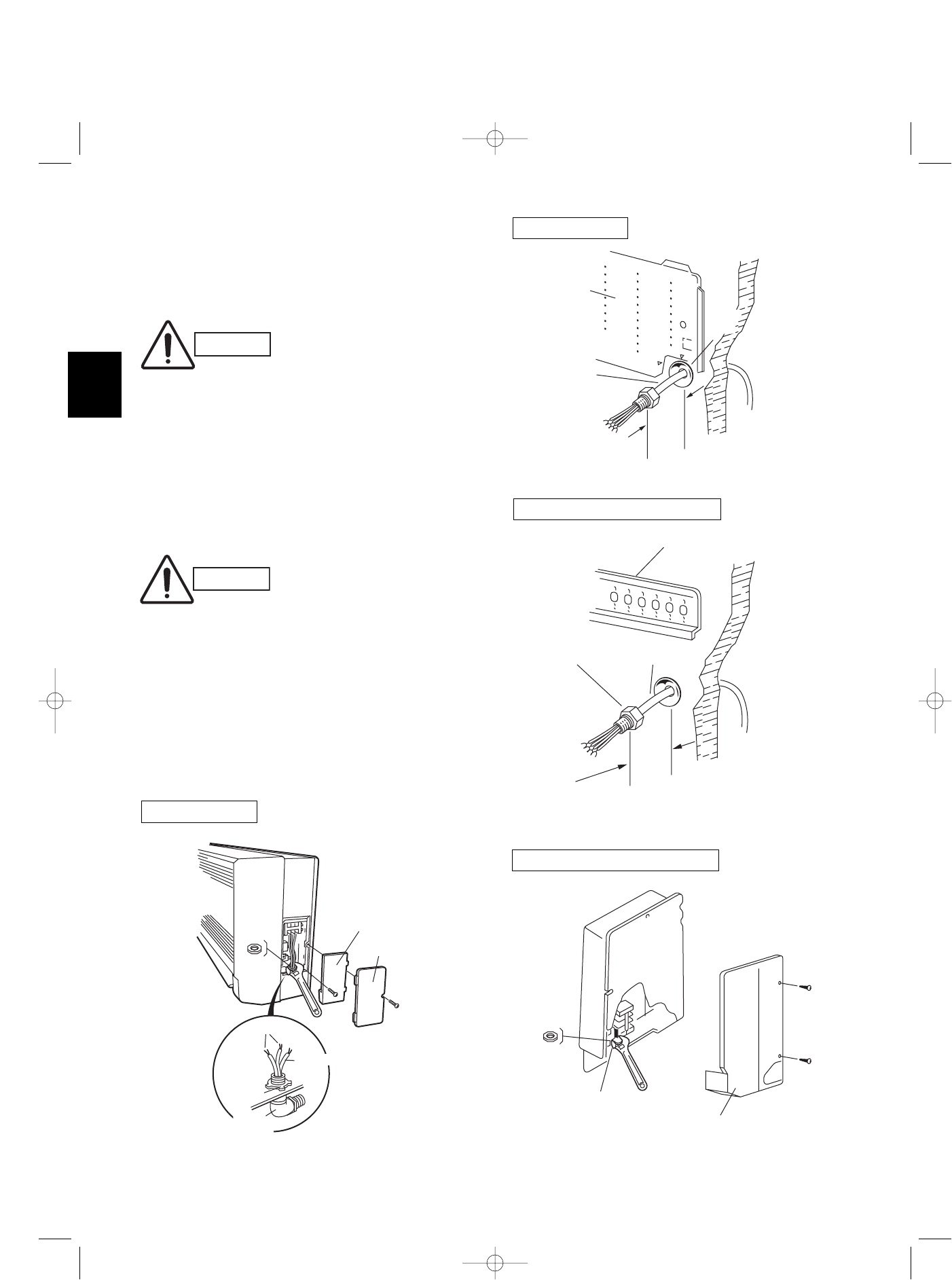
(2) Remove the side cover and the metallic cover.
(Fig. 3-60 or 3-61, depending on model.)
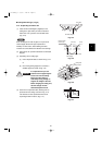
(3) Secure the conduit connector to the chassis with a
lock nut. (Fig. 3-60 or 3-61)
(4) Give some play to the inter-unit wiring from the
outdoor unit to the corresponding terminals on the
terminal plate.
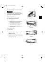
(5) Secure the metallic cover with its screw. Then
replace the side cover.
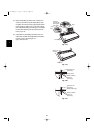
CAUTION
● Be sure to refer to the wiring
system diagram label inside
the metallic cover and carry
out the correct field wiring.
Wrong wiring can cause the
unit to malfunction.
● Check local electrical codes
and any specified wiring
instructions or limitations.
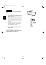
KH(S)3072R, KH(S)3672R
Fig. 3-59b
Grounding
line
Power line
Screw
Plastic cover
Metallic cover
Lock
nut
Elbow
conduit
Look nut
Lock
nut
Connector
Metallic cover
Side cover
Fig. 3-60
Fig. 3-61
KH(S)3072R, KH(S)3672R
KHH(S)2672R
Fig. 3-59a
07-115 SSHP_II 5/7/07 4:00 PM Page 44