


111
11-8-5. Indicating (marking) the indoor and outdoor unit combination number
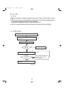
Indicate (mark) the number after automatic address setting is completed.
(1) So that the combination of each indoor unit can be easily checked when multiple units are installed, ensure that the
indoor and outdoor unit numbers correspond to the system address number on the outdoor unit control PCB, and
use a magic marker or similar means which cannot be easily erased to indicate the numbers in an easily visible
location on the indoor units (near the indoor unit nameplates).
Example: (Outdoor) 1 - (Indoor) 1-1...(Outdoor) 2 - (Indoor) 2-2...
(2) These numbers will be needed for maintenance. Be sure to indicate them.
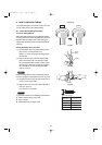
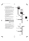
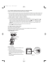
* Use the remote controller to check the addresses of the indoor units. Press and hold the button and
button for 4 seconds or longer (simple settings mode). Then press the button and select the indoor
address. (Each time the button is pressed, the address changes as follows: 1-1, 2-1, ....) The indoor unit fan
operates only at the selected indoor unit. Confirm that correct fan is operating, and indicate address on the
indoor unit.
Press the button again to return to the normal remote controller mode.
For details, refer to the separate handbook.
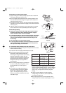
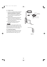
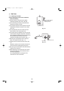
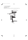
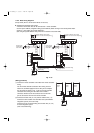
11-8-6. Main-sub remote controller control
Control using 2 remote controller switches
Main-sub remote controller control refers to the use of 2 remote controllers to control 1 indoor unit.
(A maximum of 2 remote controllers can be connected.)
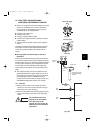
● Connecting 2 remote controllers to
control 1 indoor unit
1 2
1 2
1 2
U1U2
U1U2
Remote controller wiring
Optional
Optional
Remote controller
switch (sub)
Remote controller
switch (main)
Indoor unit
Outdoor unit
Ground
G
G
Ground
for remote
controller wiring
Ter minal plate
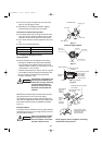
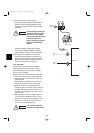
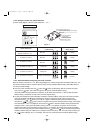
(Setting procedure)
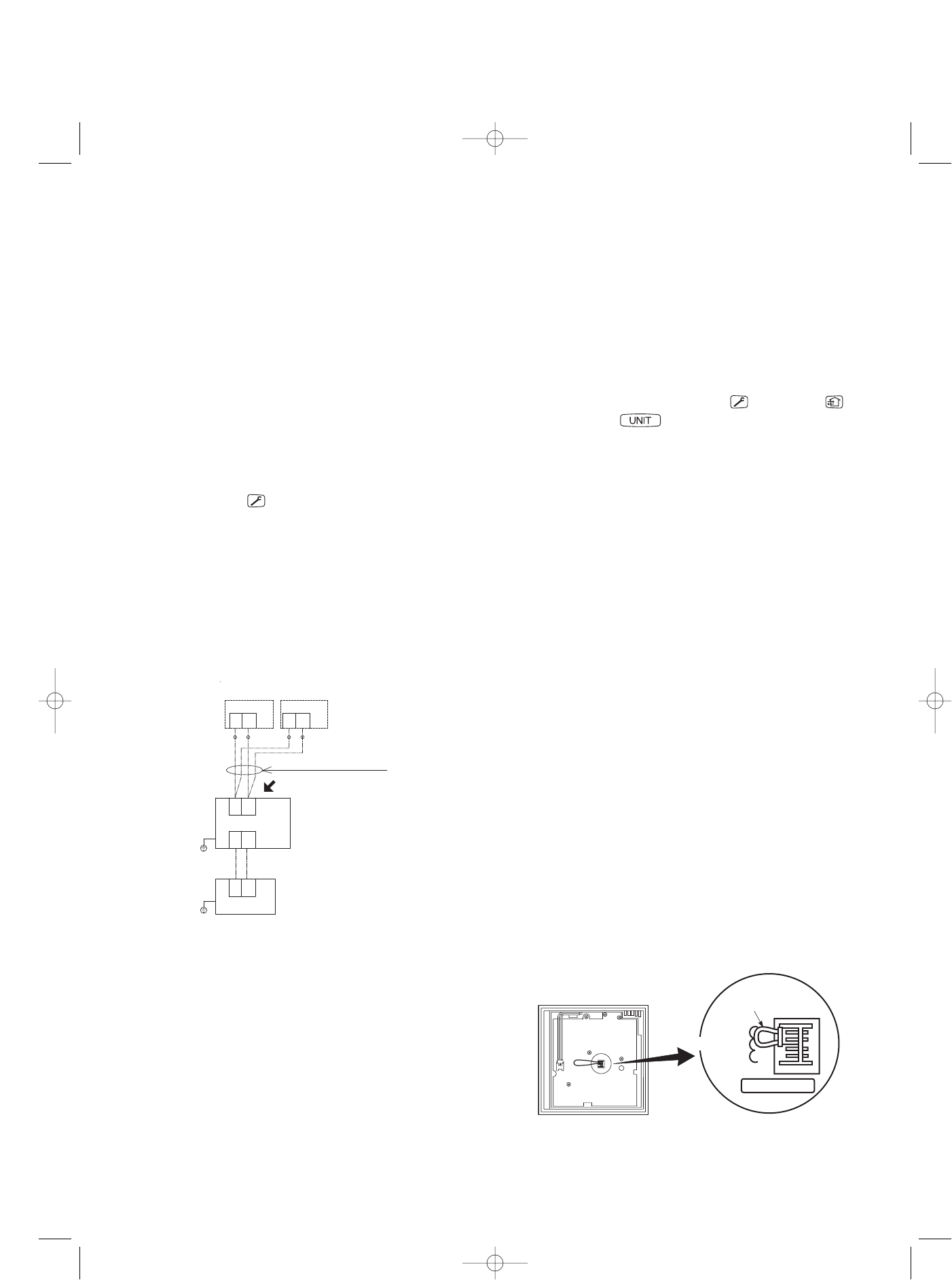
(1) Set 1 of the 2 connected remote controllers as the
main remote controller.
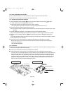
(2) On the other remote controller (sub remote
controller), change the remote controller address
connector on the reverse side of the remote controller
switch PCB from the Main position to the Sub
position.
The remote controller will now function as the sub
remote controller.
Fig. 11-8
Remote controller Remote controller
address connector
RCU. ADR
Main
Sub
RCU check
07-115 SSHP_II 5/7/07 4:00 PM Page 111