


64
RC
(WD)
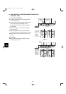
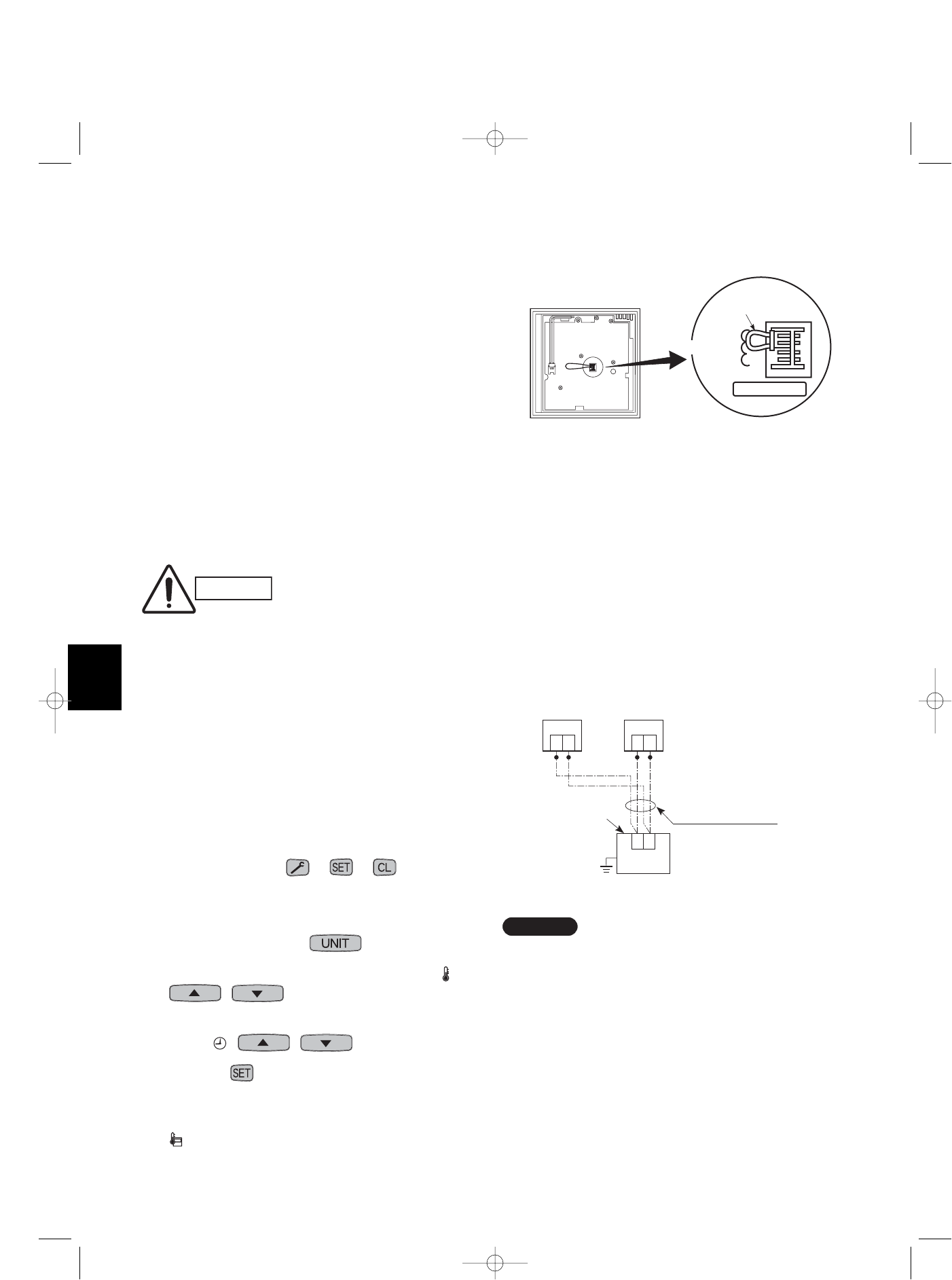
6-5. Wiring System Diagram for Multiple Remote
Controllers
■ When Installing Multiple Remote Controllers
This multiple remote controller system is used for
operating the unit(s) at different positions. (A maximum
of 2 remote controllers can be installed.)
● Setting method
To execute this control, make the setting according
to the following procedure.
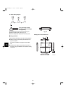
(1) Of the 2 installed remote controllers, make 1 the
main remote controller (factory-shipped state).
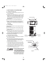
(2) On the other remote controller, change the address
connector on the PCB from main to sub position.
In this state, it functions as a sub-remote controller.
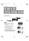
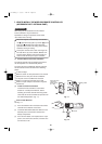
● Basic wiring diagram
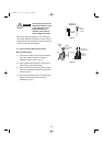
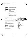
CAUTION
Install wiring correctly
(incorrect wiring will damage
the equipment).
To operate 1 indoor unit with 2 remote controllers set
at different places.
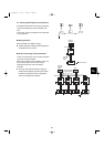
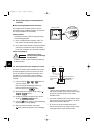
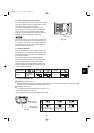
6-6. How to Switch the Indoor Temperature Sensor
The indoor unit and the remote controller both contain
an indoor temperature sensor. The sensors on either
unit can be used but normally only the sensor set on
the indoor unit is used. However, use the following
procedure if you must use the sensor on the remote
controller.
(1) Press and hold the + + buttons for
at least 4 seconds.
Note: The Unit No. first displayed is the main
indoor unit address for group control.
Note: Do not press the button.
(2) Select CODE NO. 32 with the Temp. setting ( )
/ buttons.
(3) Change the set data from 0000 to 0001 with the
Timer ( ) / buttons.
(4) Press the button. (Setting is OK if the blinking
display changes to a lit up display.)
(5) This is the usual off condition. At this time,
(remote controller) appears on the LCD display.
*1 If using 2 remote controllers, either one (main or
sub-remote controller) can be used to make settings
but only the main unit functions as the remote
controller sensor.
*2 The remote controller sensor will not function during
group control unless the group address is set in the
main remote controller indoor unit.
*3 Do not use the remote controller switch for the
remote control sensor if the remote sensor is being
used jointly with the remote controller switch.
NOTE
Remote controller Remote controller
address connector
RCU. ADR
Main
Sub
RCU check
Remote control cable
(wire it at the
installation site)
Remote control
cable terminal
board
1
2
Indoor unit
Earth
(sub)(main)
1
2
(Option)
1
2
07-115 SSHP_II 5/7/07 4:00 PM Page 64