


56
4. HOW TO INSTALL THE OUTDOOR UNIT
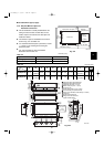
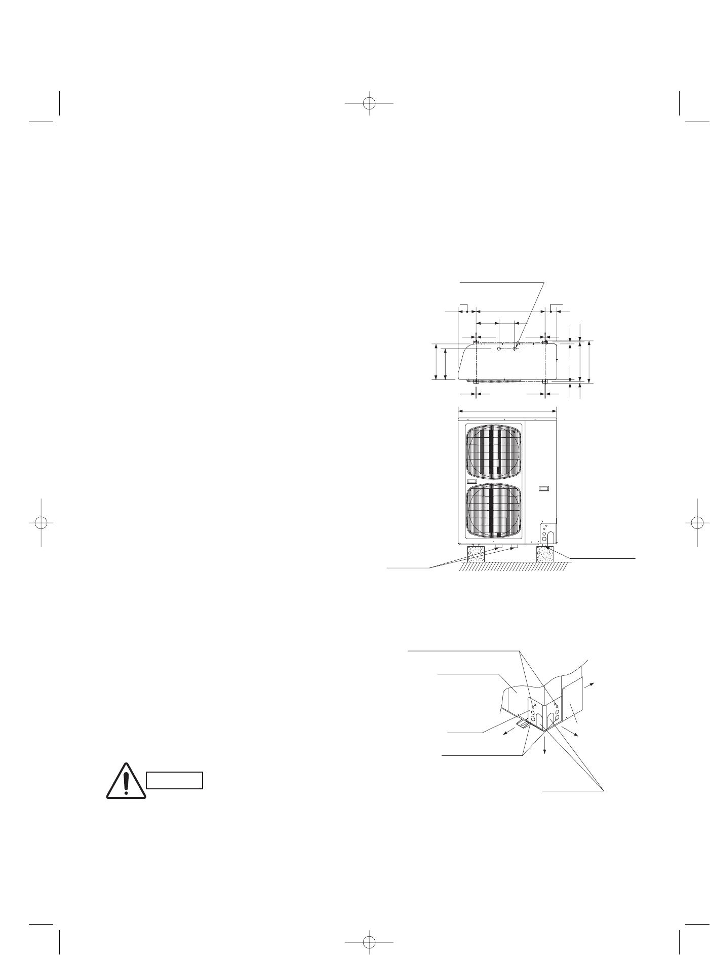
4-1. Installing the Outdoor Unit
● Use concrete or a similar material to create the base, and
ensure good drainage.
● Ordinarily, ensure a base height of 2 in. or more. If a drain
pipe is used, or for use in cold-weather regions, ensure a
height of 6 in. or more at the feet on both sides of the unit.
(In this case, leave clearance below the unit for the drain
pipe, and to prevent freezing of drainage water in cold-
weather regions.)
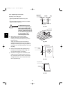
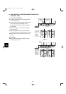
● Refer to the Fig. 4-1 for the anchor bolt dimensions.
● Be sure to anchor the feet with the anchor bolts (M10). In
addition, use anchoring washers on the top side. (Use
large square 32 × 32 SUS washers with diameters of 10.)
(Field supply)
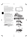
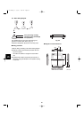
4-2. Drainage Work
Follow the procedure below to ensure adequate draining for
the outdoor unit.
● For the drain port dimensions, refer to the figure at right.
● Ensure a base height of 6 in. or more at the feet on both
sides of the unit.
● When using a drain pipe, install the drain socket (optional
part STK-DS25T) onto the drain port. Seal the other drain
port with the rubber cap supplied with the drain socket.
● For details, refer to the instruction manual of the drain
socket (optional part STK-DS25T).
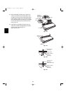
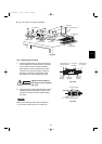
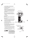
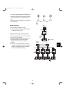
4-3. Routing the Tubing and Wiring
● The tubing and wiring can be extended out in 4 directions:
front, rear, right, and down.
● The service valves are housed inside the unit. To access
them, remove the inspection panel. (To remove the inspec-
tion panel, remove the 3 screws, then slide the panel
downward and pull it toward you.)
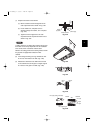
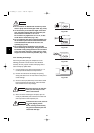
(1) If the routing direction is through the front, rear, or right,
use a nipper or similar tool to cut out the knockout holes
for the inter-unit control wiring outlet, power wiring outlet,
and tubing outlet from the appropriate covers A and B.
(2) If the routing direction is down, use a nipper or similar tool
to cut out the lower flange from cover A.
Fig. 4-1
37-3/32
11-21/32
5-29/32
8-5/8
33/64 33/64
3/4
25/32
19/32
25/6414-61/64
15-15/16
13-13/64
33/6433/64
6-47/64
4-3/8
25-63/64
Drain port (2 locations)
Drain port
Anchor bolt (M10)
Fig. 4-2
Inter-unit control wiring outlet
Inspection panel
Cover A
Cover B
Power wiring outlet
Tubing outlet
Down
Front
Rear
Right
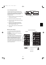
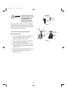
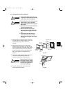
CAUTION
● Route the tubing so that it does
not contact the compressor,
panel, or other parts inside the
unit. Increased noise will result if
the tubing contacts these parts.
● When routing the tubing, use a
tube bender to bend the tubes.
Unit: inch
07-115 SSHP_II 5/7/07 4:00 PM Page 56