


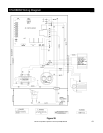
Rinnai Corporation Hydronic Furnace (37AHB) Manual 55
NOTES:
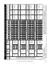
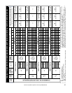
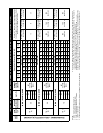
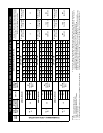
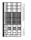
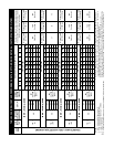
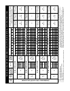
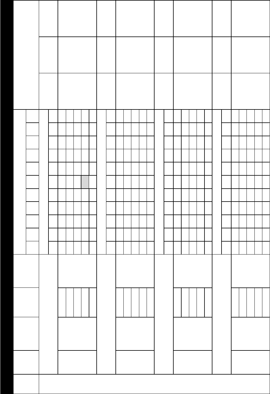
1. EWT - Entering Water Temperature (F).
2. CFM - Airflow in (Cubic Feet per Minute).
3. Legs - 3 inch diameter flexible ducts to diffusers.
4. 1 MBH = 1000 BTU/H.
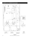
5. Shaded box represents rating point; refer to wiring diagram for factory set speed taps.
6. Number of 3” diameter legs specified in table above is for rating point only (i.e. at External Static Pressure of 0.5
in. wc. and speed TAP3, TAP1, TAP2 , TAP2 for AHB45, AHB60, AHB75, AHB90 respectively). Final leg count is
to be determined by the installing contractor and is to be based on the following formula:
NUMBER OF LEGS = TOTAL AVAILABLE CFM
(AT THE SPECIFIC ESP)
/ DESIRED CFM per LEG
(40, 50, or 60 CFM)
Example: Given the design point for AHB045 of 0.8 ESP, Low fan speed (Tap5). From table 5.0, available CFM is
569 and the desired CFM per leg is 50 CFM. Therefore, Number of Legs = 569/50 = 11.38 rounded down to 11.
0 0.1 0.2 0.3 0.4 0.5 0.6 0.7 0.8 0.9 1.0
1343 1318 1296 1270 1248 1225 1197 1168 1109 1025 889
120 41.5 40.7 40.0 39.2 38.5 37.8 37.0 36.1 34.2 31.6 27.4
130 49.6 48.6 47.8 46.9 46.1 45.2 44.2 43.1 40.9 37.8 32.8
140 57.8 56.7 55.8 54.6 53.7 52.7 51.5 50.2 47.7 44.1 38.2
150 65.9 64.7 63.6 62.4 61.3 60.1 58.8 57.3 54.5 50.3 43.6
160 73.9 72.5 71.3 69.9 68.7 67.4 65.9 64.3 61.0 56.4 48.9
1148 1128 1103 1072 1045 1012 984 955 937 908 690
120 38.9 38.2 37.4 36.3 35.4 34.3 33.3 32.3 31.7 30.8 23.4
130 46.4 45.6 44.6 43.3 42.2 40.9 39.8 38.6 37.9 36.7 27.9
140 54.3 53.4 52.2 50.7 49.4 47.9 46.6 45.2 44.3 43.0 32.6
150 63.0 61.9 60.5 58.8 57.3 55.5 54.0 52.4 51.4 49.8 37.9
160 70.5 69.3 67.8 65.9 64.2 62.2 60.4 58.7 57.6 55.8 42.4
971 942 911 880 847 817 784 751 715 680 642
120
38.2 37.1 35.9 34.6 33.3 32.2 30.9 29.6 28.1 26.8 25.3
130
45.3 43.9 42.5 41.0 39.5 38.1 36.5 35.0 33.3 31.7 29.9
140
52.8 51.2 49.5 47.8 46.0 44.4 42.6 40.8 38.9 37.0 34.9
150
60.4 58.6 56.7 54.8 52.7 50.9 48.8 46.7 44.5 42.3 40.0
160
67.9 65.9 63.7 61.5 59.2 57.1 54.8 52.5 50.0 47.5 44.9
844 810 777 734 698 665 626 581 533 504 466
120
36.3 34.8 33.4 31.5 30.0 28.6 26.9 25.0 22.9 21.7 20.0
130
42.8 41.0 39.4 37.2 35.4 33.7 31.7 29.4 27.0 25.5 23.6
140
49.8 47.8 45.8 43.3 41.2 39.2 36.9 34.3 31.4 29.7 27.5
150
55.9 53.6 51.5 48.6 46.2 44.0 41.5 38.5 35.3 33.4 30.9
160
61.9 59.4 57.0 53.8 51.2 48.8 45.9 42.6 39.1 36.9 34.2
TABLE 5.23: AIR DELIVERY AND PERFORMANCE DATA (BOTTOM OR SIDE RETURN w/ FACTORY SUPPLIED FILTER)
UNIT
SIZE
ECM
SPEED
TAP
SUPPORTS
COOLING CAP.
RANGE (TONS)
EWT (
O
F)
NOMINAL
HEATING
CAPACITY
External Static Pressure (ESP) in. W.C.
Number of 3" diameter branch legs applicable to High
Velocity Systems only. Uded only if methods other than
Table 3 is used to determine duct sizes.
TBD
See Note 6.
TBD
See Note 6.
37AHB06012KA5 + REU-VA2024WD(A)-UC
AHB60 + R63LSe2
AIRFLOW (CFM)
TAP 1
(H)
3.0
NET
HEATING
CAPACITY
(MBH)
20 24
AHB60 + R63LSe2
AIRFLOW (CFM)
TAP 2
(MH)
2.5
NET
HEATING
CAPACITY
(MBH)
TBD
See Note 6.
AHB60 + R63LSe2
AIRFLOW (CFM)
TAP 4
(ML)
2.0
NET
HEATING
CAPACITY
(MBH)
TBD
See Note 6.
Minimum Legs @
60 CFM/Leg
AHB60 + R63LSe2
AIRFLOW (CFM)
TAP 5
(L)
1.5
NET
HEATING
CAPACITY
(MBH)
Minimum Legs @
60 CFM/Leg
Optimal Legs @
50 CFM/Leg
Maximum Legs @
40 CFM/Leg
Minimum Legs @
60 CFM/Leg
Optimal Legs @
50 CFM/Leg
Maximum Legs @
40 CFM/Leg
30
Optimal Legs @
50 CFM/Leg
Maximum Legs @
40 CFM/Leg
Minimum Legs @
60 CFM/Leg
Optimal Legs @
50 CFM/Leg
Maximum Legs @
40 CFM/Leg
TBD
See Note 6.
TBD
See Note 6.
TBD
See Note 6.
TBD
See Note 6.
TBD
See Note 6.