


Rinnai Corporation Hydronic Furnace (37AHB) Manual 33
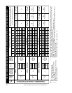
0 0.1 0.2 0.3 0.4 0.5 0.6 0.7 0.8 0.9 1.0
948 921 891 868 841 819 795 772 701 596 567
120 31.4 30.5 29.5 28.7 27.8 27.1 26.3 25.6 23.2 19.7 18.8
130 37.4 36.3 35.2 34.3 33.2 32.3 31.4 30.5 27.7 23.5 22.4
140 46.0 44.7 43.2 42.1 40.8 39.7 38.6 37.4 34.0 28.9 27.5
150 52.3 50.8 49.1 47.9 46.4 45.2 43.9 42.6 38.7 32.9 31.3
160 59.3 57.6 55.7 54.3 52.6 51.2 49.7 48.3 43.8 37.3 35.5
921 891 864 836 812 788 768 742 699 594 559
120 31.8 30.8 29.9 28.9 28.1 27.2 26.5 25.6 24.2 20.5 19.3
130 37.2 36.0 34.9 33.8 32.8 31.8 31.0 30.0 28.2 24.0 22.6
140 45.8 44.3 42.9 41.6 40.4 39.2 38.2 36.9 34.7 29.5 27.8
150 52.1 50.4 48.9 47.3 45.9 44.6 43.4 42.0 39.5 33.6 31.6
160 58.7 56.7 55.0 53.2 51.7 50.2 48.9 47.3 44.5 37.8 35.6
803 768 740 712 682 652 628 596 569 541 510
120 31.2 29.8 28.7 27.7 26.5 25.3 24.4 23.2 22.1 21.0 19.8
130 35.3 33.8 32.6 31.3 30.0 28.7 27.6 26.2 25.0 23.8 22.5
140 41.1 39.3 37.8 36.4 34.9 33.3 32.1 30.5 29.1 27.7 26.1
150 49.0 46.8 45.1 43.4 41.6 39.7 38.3 36.3 34.7 33.0 31.1
160 55.0 52.6 50.7 48.7 46.7 44.6 43.0 40.8 38.9 37.0 34.9
20
13 16 20
Minimum Legs @
60 CFM/Leg
Optimal Legs @
50 CFM/Leg
Maximum legs @
40 CFM/Leg
AHB45 + RC80HPi(e)
AHB45 + RC80HPi(e)
AHB45 + RC80HPi(e)
13 16
TAP 5
(L)
1.5
NET
HEATING
CAPACITY
(MBH)
AIRFLOW (CFM)
TAP 4
(M)
Minimum Legs @
60 CFM/Leg
Optimal Legs @
50 CFM/Leg
Maximum legs @
40 CFM/Leg
16 20
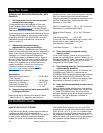
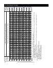
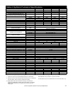
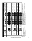
TABLE 5.1: AIR DELIVERY AND PERFORMANCE DATA (BOTTOM OR SIDE RETURN w/ FACTORY SUPPLIED FILTER)
UNIT
SIZE
ECM
SPEED
TAP
37AHB04508KA5 + REU-KA2530FFUD(WD)-US
TAP 3
(H)
AIRFLOW (CFM)
NET
HEATING
CAPACITY
(MBH)
2.0
NET
HEATING
CAPACITY
(MBH)
2.0
13
SUPPORTS
COOLING CAP.
RANGE (TONS)
EWT (
O
F)
AIRFLOW (CFM)
NOMINAL
HEATING
CAPACITY
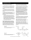
External Static Pressure (ESP)
Number of 3" Diameter Branch Legs applicable to High
Velocity Systems Only. Used only if methods other
than Table 3 is used to determine duct sizes.
Minimum Legs @
60 CFM/Leg
Optimal Legs @
50 CFM/Leg
Maximum legs @
40 CFM/Leg
NOTES:
1. EWT - Entering Water Temperature (F).
2. CFM - Airflow in (Cubic Feet per Minute).
3. Legs - 3 inch diameter flexible ducts to diffusers.
4. 1 MBH = 1000 BTU/H.
5. Shaded box represents rating point; refer to wiring
diagram for factory set speed taps.
6. Number of 3” diameter legs specified in table above is for rating point only (i.e. at External Static Pressure of 0.5 in. wc. and
speed TAP3, TAP1, TAP2 , TAP2 for AHB45, AHB60, AHB75, AHB90 respectively). Final leg count is to be determined by
the installing contractor and is to be based on the following formula:
NUMBER OF LEGS = TOTAL AVAILABLE CFM
(AT THE SPECIFIC ESP)
/ DESIRED CFM per LEG
(40, 50, or 60 CFM)
Example: Given the design point for AHB045 of 0.8 ESP, Low fan speed (Tap5). From table 5.0, available CFM is 569 and
the desired CFM per leg is 50 CFM.
Therefore, Number of Legs = 569/50 = 11.38 rounded down to 11.
TBD
See Note 6.
TBD
See Note 6.
TBD
See Note 6.
TBD
See Note 6.
TBD
See Note 6.
TBD
See Note 6.
in. W.C.