


Rinnai Corporation Hydronic Furnace (37AHB) Manual 15
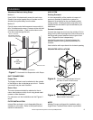
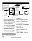
Electrical Connection to Control Box
1. Route the furnace power wires through aligned
holes in casing and Control Box and make field
wire connections in Control Box. Use best
practices for wire bushings, strain relief, etc.
Field wiring to the unit must be grounded and
conform to the National Electrical Code C22.1 Part
1 - latest edition. Use only UL listed conduit and
conduit connectors to connect supply wires to the
unit and provide appropriate grounding.
Grounding may also be accomplished by
grounding the control box per appropriate local
codes. Electric wires that are field installed shall
conform to the temperature limitation for 63° F
(35° C) rise when installed in accordance with
instructions. Refer to Table 4 for specific furnace
electrical data.
2. Route and secure field ground wire to ground
screw on Control Box.
3. Connect line voltage leads as shown in Figure 13.
4. Reinstall cover to Control Box. Ensure that wires
are not pinched between cover and edge of
Control Box.
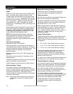
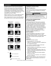
24V Control System Connections to Unit’s Printed-
Circuit Board (PCB):
Refer to Figures 25 through 27 for factory wiring
details. For low voltage connections between the unit
and the thermostat, use No. 18 AWG color-coded,
insulated (63° F / 35°C minimum) wires. (Refer to
Figures 16 through 19.)
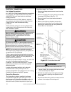
Installation
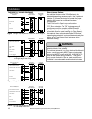
Failure to follow this warning could result in a fire. Do
not use aluminum wire between the Hydronic Furnace
and the disconnect switch. USE COPPER WIRE
ONLY.
WARNING
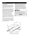
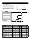
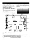
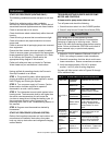
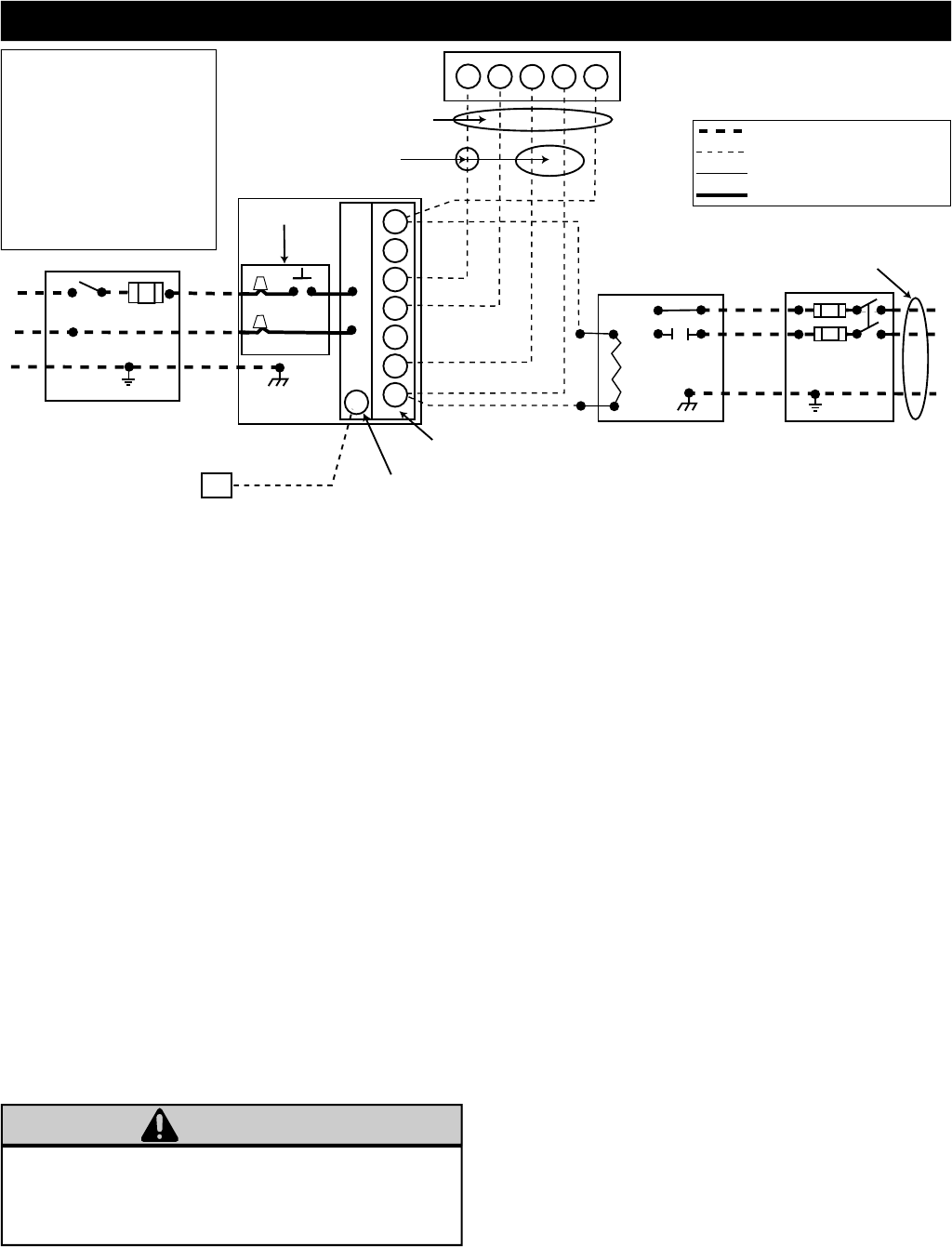
Figure 13: Field Wiring Diagram
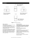
NOTES:
1. Connect Y1 terminal as
shown for proper operation.
2. Rinnai thermostats require a
“C” terminal connection as
shown.
3. If any of the original wire, as
supplied, must be replaced,
use the same type or
equivalent wire.
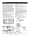
Low Voltage Connections:
These units use a grounded 24 volt AC low voltage
circuit and require at least a Single stage heating and
a Single stage cooling thermostat.
The “R” terminal is the hot terminal and the “C”
terminal is grounded.
“G” terminal is the fan input.
“Y1” terminal is the compressor Stage 1 input.
“Y2” terminal is the compressor Stage 2 input.
“O” terminal is the reversing valve input. The
reversing valve must be de-energized for heating
mode.
“R” terminal is 24 VAC hot.
“C” terminal is 24 VAC grounded.
“W” terminal is the heat input. This terminal also
energizes the emergency heat if configured for heat
pump.
W
G
R C
Y1
Y1
Y2
W
G
O
R
C
P3
FS
BLK
BLK
WHT
WHT
GND
GND
HYDRONIC FURNACE
115 Volt Fuse Disconnect
(Field Supplied)
Flow Sensor
(Packaged with Unit)
5 Wire
3 Wire Heating Only
Single Stage
Thermostat
(Available Accessory)
24 Volt FS / WH Connector
24 Volt Terminal Block
Disconnect
(Field Supplied)
208 / 230 Volt
Single Phase
Control Box
PCB
Condensing Unit
(Field Supplied)
Field 115, 208 / 230 Volt Wiring
Field 24 Volt Wiring
Factory 24 Volt Wiring
Factory 115 Volt Wiring
Junction Box
L1
L2