


16
Rinnai Corporation Hydronic Furnace (37AHB) Manual
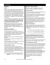
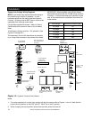
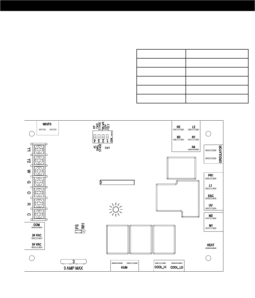
FLOW SENSOR
CONNECTIONS
SW1 SET-UP SWITCH
AND HEATING BLOW
OFF DELAY
24 V THERMOSTAT
TERMINALS
TRANSFORMER 24 V
CONNECTIONS
P3
P4
P1
3AMP FUSE
OPERATING MODE
JUMPER (SHUNT)
STATUS LED LIGHT
115 VAC (L2)
NEUTRAL
CONNECTIONS
PUMP
CONNECTIONS
115 VAC (L1) LINE
VOLTAGE
CONNECTION
FAN
PARK
FAN
CONNECTION
HEATING
FAN
CONNECTION
COOLING
HUMIDIFIER CONNECTIONS
(DRY CONTACT) 24 VAC OR
115 VAC
FLASH UPGRADE
CONNECTION
(FACTORY ONLY)
u1
AN1
Installation
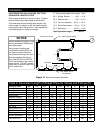
Figure 14: Hydronic Furnace Control Board
P7
Notes:
1. For proper operation of an open loop system with the flow sensor refer to Figures 11 and 14; Note that the
jumper (shunt) position on the PCB “point P7” MUST be in the FS position.
2. When changing the shunt position ensure that the unit’s power is turned off.
Wire Gauge Maximum Distance (feet)
20 gauge 45
18 gauge 60
16 gauge 100
14 gauge 160
12 gauge 250
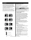
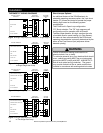
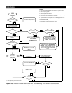
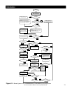
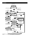
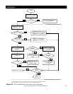
System Low Voltage Wiring Diagrams
NOTE: Local codes may require thermostat wiring to
be routed through conduit or raceways. In such
instances splices can be made inside the Hydronic
Furnace. All wiring must be NEC Class l and must be
separated from incoming power leads.
Provide field supplied disconnect. Refer to Table 4
(Specifications) for maximum fuse or circuit breaker
sizes.
Transformer is factory wired for 115v operation. (See
Figures 27 through 29.)
The secondary circuit of the transformer is protected
by a 3-amp fuse mounted on the printed-circuit board.
IMPORTANT: Where possible, use a Rinnai factory
authorized thermostat with the 37AHB series Hydronic
Furnaces. If a thermostat other than specified is used,
refer to the manufacturer’s installation instructions for
further details.