


28
Rinnai Corporation Hydronic Furnace (37AHB) Manual
The updated Rinnai Hydronic Furnace (with ECM
technology) will sustain total external static pressures
(ESP) of up to 1.0 in. w. g.; still, it is incumbent upon
the designer to devise a system that will work within
the parameters hereafter set forth in this manual. To
satisfy the above, and to take maximum advantage of
the increased available pressure of said Rinnai
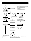
Selection Guide
GENERAL UNIT SELECTION PROCEDURE (WITH
EXAMPLE)
I. Define hot water load for the total required
domestic hot water usage:
To help with the sizing and selection of your new
Rinnai Tankless Water Heater (TWH), refer to our
Website at: http://www.rinnai.us
or contact Rinnai’s
Application Engineering Department at: 800-621-9419
As an example let us assume that the selected Rinnai
Tankless Water Heater for your whole house solution
is the REU-KA2530FFUD-US (RC80HPi) and your
calculated heat gain and heat loss values are as
stated in section II.
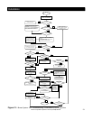
II. Determining cooling and heating
requirements for the given structure:
The ACCA's Manual J Residential Load Calculation
method is the established trade standard, approved by
ANSI, for the correct sizing and selection of Heating,
Ventilation, Air-Conditioning and Refrigeration
(HVACR) equipment in residential homes. Refer to
Manual J latest edition; the text in question offers an
all-inclusive new approach to ensure that Indoor Air
Quality (IAQ) systems are as efficient, safe, and
healthy as possible. Visit the Air Conditioning
Contractors of America website at: http://
www.acca.org or contact a qualified HVACR
contractor for further assistance.
Assumptions:
Required Cooling Capacity ……….……..34,500 Btuh
(Total Capacity)
Required Heating Capacity…………..…..58,000 Btuh
Evaporator Air Quantity………………..…1200 CFM
Calculated Ductwork ESP………….…….0.2 in. WC
Electrical Characteristics…………………15-1-60
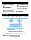
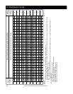
III. Determine total external static pressure (ESP)
at design conditions:
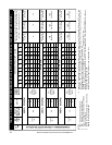
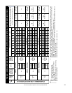
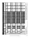
Before using the Air Delivery and Capacity Charts
(Table 5.0 thru 5.17), determine the total static
pressure required. From the given example, note the
Wet Coil Pressure Drop (from the field supplied
Evaporative Cased Coil Installation Instructions), and
the Filter Pressure Drop. Determine both static
pressures at 1200 CFM:
Wet Coil Pressure Drop……0.21 in. WC (From Coil
Manufacturer’s Installation Instructions).
External Static Pressure…...0.2 in. WC (Ductwork
etc.)
Filter Pressure Drop………..0.0 in. WC
(0.0 inches if the included Rinnai filter is used; 0.08 if
another filter is used. Refer to the filter’s
manufacturer’s instructions).
Total Static Pressure..….... 0.49 in. WC
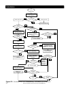
IV. Select unit based on required cooling
capacity airflow:
For an initial selection, choose a unit size that will
provide the required airflow. Refer to Tables 5.3 - Air
Delivery and Capacity Chart. Note that at 0.5 ESP the
37AHB06012KA5 unit will deliver 1225 cfm when
configured for HIGH Speed (Tap 1).
V. Select heating capacity of unit to provide the
requisite design condition:
From the nominal capacity section of said table; the
37AHB060 units (Table 5.3), note that the unit
37AHB06012KA5 (as selected above) when matched
with the REU-KA2530FFUD (RC80HPi) TWH will
provide 58.1 MBH (58,100 Btuh) at an entering water
temperature (to Hydronic furnace) of 150 OF.
VI. Select unit that corresponds to power source
available:
Refer to Model Number Nomenclature; note that the
eleventh digit denotes the voltage code; therefore the
“K” model (37AHB06012KA5) unit is the unit that
should be selected for the above stated hypothetical
conditions. This unit is designed to operate at
115/120v -1ph - 60hz.
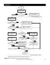
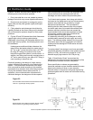
HIGH VELOCITY DUCT SYSTEMS:
A high velocity air delivery system employs higher air
velocities and static than that requisite for a
conventional ducting system. Specifically, the design
of such system requires a compromise between
smaller duct sizes and increased fan pressure.
Air Distribution Guide