


Rinnai Corporation Hydronic Furnace (37AHB) Manual 17
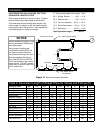
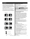
Dip Switch Options (Smart Operating System):
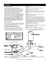
The Rinnai® exclusive Smart Operating System is a
feature of your 37AHB series Hydronic Furnace’s
control system that is designed to allow the installer
(via DIP Switch – SW1) to configure the unit for single
or two stage, A/C or Heat pump systems with
selectable heat bower off delay.
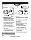
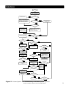
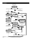
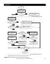
Refer to Figures 14 and 15 for the proper dip switch
setting to be used with the desired configuration.
When viewed with the Furnace in the upflow position,
the dip switch will be as shown below (upside down.
Installation
Figure 15: Dip Switch Positions
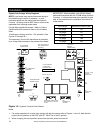
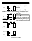
THERMOSTAT INSTALLATION:
Safety Considerations:
All wiring must conform to local and national electrical
codes. Improper wiring or installation may damage
thermostat.
INSTALLATION CONSIDERATIONS:
Air Conditioner Model:
The Standard Model A/C thermostat may be wired
with or without connecting a common wire between
the indoor equipment and the thermostat. However, it
is recommended to use a common wire whenever
possible. Without a common wire this thermostat
becomes "power stealing." This means it will need to
steal a small amount of power from the equipment to
which it is connected. When "power stealing"
connection is used, the supplied 270 ohm resistor
must be connected at the indoor unit.
Heat Pump Model:
The Standard Model HP thermostat is not "power
stealing" and MUST have both ‘R’ and ‘C’ wires
connected to operate properly. This thermostat uses a
green LED to indicate auxiliary/emergency heat
operation.
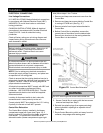
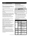
Installation:
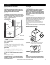
Thermostat should be mounted
• approximately 5 ft. (1.5 m) from floor
• close to or in a frequently used room, preferably on
an inside partitioning wall
• on a section of wall without pipes or duct work.
Thermostat should NOT be mounted
• close to a window, on an outside wall, or next to a
door leading to the outside.
• exposed to direct light and heat from a lamp, sun,
fireplace, or other heat-radiating object which may
cause a false reading.
• close to or in direct airflow from supply registers
and return-air grilles
• In areas with poor air circulation, such as behind a
door or in an alcove
Refer to Figures 16 through 19 for thermostat wiring
diagram and thermostat installation instructions for
further details.
SINGLE-STAGE A/
C
CONFIGURATION
(DEFAULT)
TWO-STAGEA/C
CONFIGURATION
1
O
N
2 3 41
O
N
2 3 4
SINGLE-STAGE HP
CONFIGURATION
TWO-STAGE HP
CONFIGURATION
1
O
N
2 3 41
O
N
2 3 4
30 SECONDS OFF
DELAY (DEFAULT)
60 SECONDS OFF
DELAY
1
O
N
2 3 41
O
N
2 3 4
90 SECONDS OFF
DELAY
120 SECONDS OFF
DELAY
1
O
N
2 3 41
O
N
2 3 4
WARNING
Before installing thermostat, turn off all power to unit.
There may be more than one power disconnect.
Electrical shock can cause personal injury or death.
1
O
N
Key:
Switch is in the ON position.
Switch does not affect this setting.
1
O
N
Switch is in the OFF position.