


Rinnai Corporation Hydronic Furnace (37AHB) Manual 11
Installation
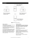
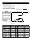
Hydraulic Resistance of Fittings, Valves, and Other
Devices:
Before the total hydraulic resistance of a piping circuit
can be found, the individual hydraulic resistances of all
fittings, valves, or other such components must be
determined. One approach is to consider each fitting,
valve, or other device as an equivalent length of
copper tube of the same pipe size (see Table 2).
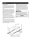
By using the equivalent length of piping for all
components in the circuit, the circuit can be treated as
if it were a single piece of pipe having a length equal
to the sum of the actual pipe length, the total
equivalent lengths of all fittings, valves, or other
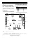
devices. Refer to Figure 10 and the associated
computation of equivalent lengths.
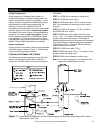
Pipe Sizing Considerations:
When selecting a pipe size for a given flow rate, the
resulting average flow velocity should be between 2
and 4 feet per second.
At water flow velocities of approximately 2 feet per
second, flowing water will carry air bubbles along a
vertical pipe. Average flow velocities of 2 feet per
second or higher can draw along air bubbles in a
downward flow. At the above stated velocities air
bubbles shall be routed to an air separator where they
can be collected and discharged from the system.
Use Taco 4900 series air separator, Model 49-075, or
equivalent (field supplied).
Average flow velocities higher than 4 feet per second
could cause flow noise and should be avoided.
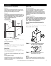
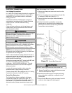
Expansion Tanks:
All liquids used in hydronic heating systems expand
when heated. For all practical purposes, liquids are
incompressible. Any container completely filled with a
liquid and sealed from the atmosphere will experience
a rapid increase in pressure as the liquid is heated.
To prevent this from occurring, all modern hydronic
systems MUST be equipped with an expansion tank.
Refer to expansion tank manufacture’s instructions for
proper sizing and installation.