


10
Rinnai Corporation Hydronic Furnace (37AHB) Manual
Installation
PLUMBING
Codes:
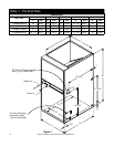
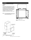
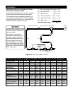
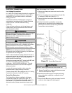
Observe all local sanitary codes when installing water
lines. The water supply mating connection to the
37AHB Hydronic Air-Handling Units are made via the
two (3/4 in. Dia. X 2-1/2 in. Long) copper stubs to the
front-left of the unit labeled “WATER IN” and “WATER
OUT” (see Figure 1). Mating connectors to be two
field supplied 3/4 in. FNPT-sweat ends or two field-
supplied 3/4 in. SharkBite type FNPT-push fitting ends
or equivalent.
All associated hydronic piping MUST comply with ICC,
UPC and any other local codes or ordinances having
jurisdiction. USE POTABLE GRADE COPPER OR
OTHER PIPING MATERIALS. MATERIALS TO BE
LEAD FREE APPURTENANCES ONLY.
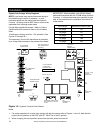
NOTE: Recommended piping, fittings, valves and
other appurtenances (exclusive of those indicted as
accessories that are available through Rinnai
distribution) called for in piping schematics to be field-
supplied.
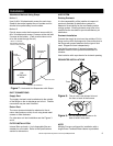
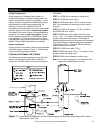
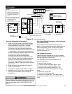
Flow Sensor Installation:
(Required for Open Loop Systems)
Care must be taken to ensure that the flow sensor is
not damaged due to excessive tightening. The torque
must not exceed the maximum limit stated below. The
installation should be checked to ensure that no
leaking is evident.
Mating connectors to be (2) 3/4” FNPT fittings (field
supplied).
Pipe-work/connector alignment is imperative (avoid
bending stress).
Polytetrafluoroethylene (PTFE) thread seal tape (teflon
tape), or equivalent, is recommended.
Tighten fittings to maximum torque of 15lb/ft (20Nm).
Soldering Copper Tubing:
The common method of joining copper tubing in
hydronic heating systems is soft soldering. Plumbing
codes do not allow solders containing lead to be used
for domestic water service. USE ONLY 95/5 tin/
antimony solder for all piping systems that incorporate
a domestic water supply.
Note: Precautions must be taken during soldering to
avoid debris or solder from lodging in piping
system.
Mechanical Joining of Tubing:
Where used, refer to the respective mechanical
system manufacturer’s installation instructions.
Tubing Insulation:
Any tube conveying fluid at a temperature greater than
that of the surrounding air releases heat.
Insulate all accessible hot water lines and associated
valves with material, such as expanded neoprene or
polyurethane 3/8-in. to 1⁄2-in. thick.
Match the pipe sleeve's inside diameter to the pipe’s
outside diameter for a snug fit. Place the pipe sleeve
so the seam will be face down on the pipe. Tape,
wire, or clamp insulation every foot or two to secure it
to the pipe. If taping is desired, use acrylic tape
instead of duct tape.
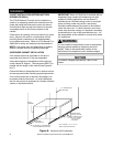
Copper Tubing Support:
Copper tubing must be properly supported to prevent
sagging or buckling. On horizontal runs with hard
temper tubing, the following maximum support spacing
is suggested:
• 1/2 in. to 3/4 in. tube: 5 feet maximum spacing
• 1 in. to 1-1/4 in. tube: 6 feet maximum spacing
• 1-1/2 in. to 2 in. tube: 8 feet maximum spacing
The above suggested spacing does not account for
extra weight of piping components such as an
expansion tank, etc. When such components are
present the piping should be supported immediately
adjacent to the component.
On vertical runs, copper tubing should be supported at
each floor level or at a maximum of every 10 feet.
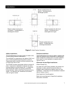
Thermal Expansion of Piping:
In all hydronic systems, piping undergoes temperature
swings as the system operates. This causes changes
in the length of the piping due to thermal expansion.
If the piping is rigidly mounted, this expansion can
cause annoying popping or squeaking sounds and in
extreme cases, the piping can even buckle.
To counter expansion movement, design piping
circuits with sufficient elbows, tees or expansion loops
(only used in large systems) or piping supports that
allow the tubing to expand and contract freely.
Another alternative is to install an expansion
compensator fitting capable of absorbing the
movement.