Quadra-Fire • QFP38 Series • 4061-300 Rev i • 9/09 53
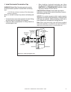
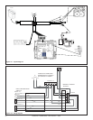
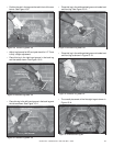
BLACK
WHITE
GROUND
14-2 with
Ground Romex
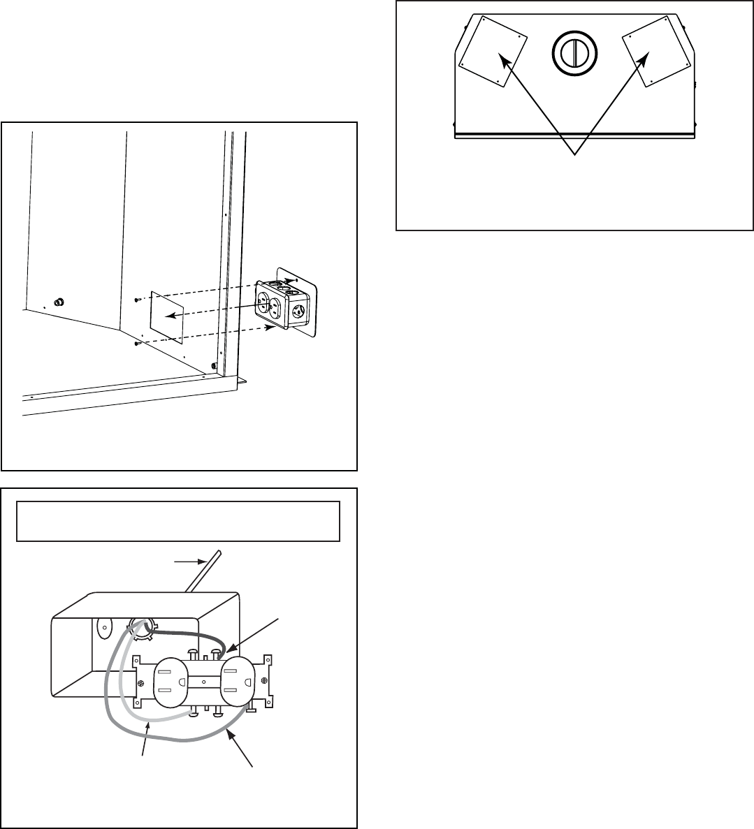
Figure 13.4 Junction Box Detail
14-2 with ground Romex is the recommended wiring
to the appliance junction box.
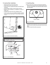
D. Junction Box Installation
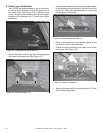
• Remove junction box from outer shell.
• Remove front cover from junction box.
• Knock out hole in junction box back and install Romex
connector.
• Feed necessary length of wire through connector.
• Make all wire connections to receptacle as shown in
Figure 13.4.
• Reassemble jumction box with receptacle inside.
• Insert junction box and receptable assembly through
hole in outer shell (see Figure 13.3) and fasten with two
screws.
Figure 13.3 Remove Junction Box Assembly
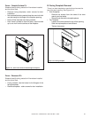
E. Heat-Zone-Gas
Install the Heat Zone Kit before enclosing the appliance.
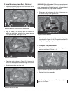
• Remove one of two square cover plates for each kit from
the top of the appliance. Set the screws aside, discard
the cover plate.
• Replace the cover plate with the heat zone collar from
the kit. Use the three screws removed from the cover
plate.
• Return to Heat-Zone-Gas instructions.
Cover Plates
Figure 13.5 Cover Plates


