48
Sensaphone
®
ISACC Instruction Manual
High Power Solid State Relay - The 25 Amp high power solid state relay (FGD-0020) is
available from Phonetics. See Appendix D for accessory information. The ISACC enclosure is
predrilled to mount as many as 8 high power solid state relays using two #6-32 ˘” machine
screws. See Appendix C for mounting diagrams.
NOTE: Do not use a high power solid state relay when a lower power relay will be suffi-
cient. Solid state relays require a certain minimum current to switch (see page 54 for solid
state relay specifications). If a lower power relay is sufficient to switch the required cur-
rent, but you have a high power relay wired, the output may not switch. Likewise, a
certain amount of leakage current also occurs. With a high power relay, this could be
sufficient to cause unintended switching of an output.
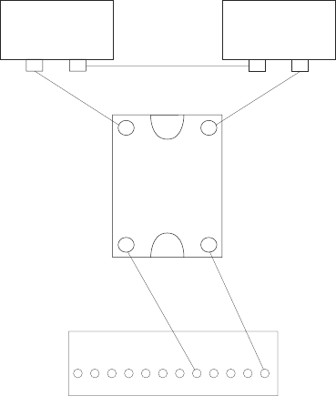
To use a high power solid state relay:
1. Mount the relay in the ISACC enclosure so that terminals 3 and 4 are closest to the
ISACC circuit board.
2. Wire terminal 3 on the relay to the 5V terminal on the DIGITAL OUTPUTS
terminal block.
3. Wire terminal 4 on the relay to one of the digital output terminals (1-8).
4. Wire terminal 2 on the relay to one of the terminals on the AC device.
5. Wire the other terminal on the AC device to the NEUTRAL terminal on the AC
external power source.
6. Wire the HOT terminal on the AC external power source to terminal 1 on the
relay.
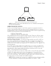
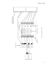
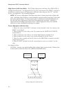
See diagram below:
CAUTION: Exercise care when handling high voltage, high current circuits. Failure to do
so may result in electrical shock, fire, and/or serious bodily harm.
AC power source
1 2
- +
4 3
DIGITAL OUTPUTS
8 7 6 5 4 3 2 1 C 12V C 5V
AC device
HOT NEUTRAL
High power solid
state relay
Wiring a high power solid state relay


