38
Sensaphone
®
ISACC Instruction Manual
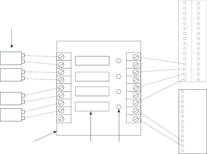
To wire the logic I/O (right side) to ISACC:
1. Attach terminal 1 (on the right side) to 5 VDC on the ISACC power supply termi-
nal block. Attach terminal 2 to one of the C (common) terminals on the ISACC
power supply terminal block.
2. Connect an odd-numbered terminal (3, 5, 7, or 9) to one of the ISACC input
terminals (1-16) on the bottom row terminal block. The shunt for this input must be
in the TEMP position.
To wire the field I/O (left side) to the input device:
If the input device is DC:
1. Connect ground from the outside device to the odd-numbered terminal (3, 5, 7, or
9) on the rack.
2. Connect the positive voltage from the outside device to the even-numbered termi-
nal (2, 4, 6, or 8) on the rack.
If the input device is AC, polarity does not matter and either wire can be connected to a
terminal pair on the rack.
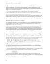
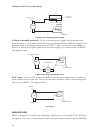
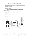
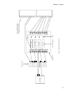
See sample diagram below:
9
8
7
6
5
4
3
2
1
9
8
7
6
5
4
3
2
1
DC input
DC input
2I0-4A
LEDSolid state modules
AC input
AC input
DC device
+
G
DC device
+
G
AC device
AC device
Input devices
POWER
EG 24 24 BAT C 20V C 15V C 12V C 5V C
AC AC
4-module rack
INPUTS
1 2 3 4 5 6 7 8 9 10 11 12 13 14 15 16
Wiring AC and DC input modules using a 4-module rack
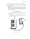
DIP CONNECTOR FOR A 16-MODULE RACK
If you need to use all 16 inputs for monitoring AC or DC voltage, you may simplify your
wiring by using a 16-module rack (Potter & Brumfield 2IO16), with a 50-pin ribbon cable
with a card edge connector on one end and a 50-pin socket connector on the other end. The
socket connector connects to the ISACC unit and the card edge connector connects to the


