35
Chapter 4: Inputs
INPUT TERMINAL BLOCK
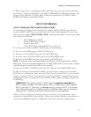
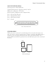
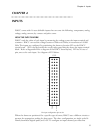
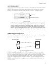
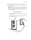
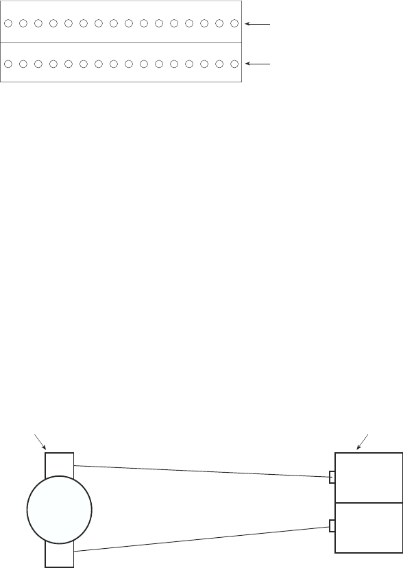
On the circuit board, each input terminal is located on the double row terminal block labeled
INPUTS. The bottom row is the positive input terminal and the top row is the common
terminal. All commons are the same and are internally connected. See diagram below:
INPUTS
1 2 3 4 5 6 7 8 9 10 11 12 13 14 15 16
Commons
Input terminal screws
Input terminal block
NOTE: If you are using the ABS plastic enclosure, you must remove the top cover to
access the circuit board. After wiring is completed, reinstall the top cover. All wiring
should be properly fitted through the strain relief clamps. Strain relief is provided in
the ISACC enclosure to prevent wiring from being pulled from the circuit board or
damaged while passing through the enclosure. To use, thread wires through the clamp
and clear rubber bushing. Position the bushing in the clamp and tighten the screws on
either side so that the wiring does not move.
WIRING SENSORS TO THE INPUTS
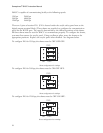
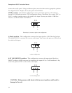
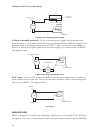
Dry contact/Thermistor/Pulse count - To use a dry contact sensor, thermistor, or pulse
counter on an input, wire one lead to the numbered screw of an input terminal and the other
lead to the corresponding common screw. See diagram below:
COMMON
INPUT
Input terminal pair
Dry contact sensor
NO / NC
Dry contact/ Thermistor/Pulse count sensor
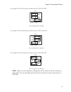
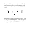
4-20mA (internally powered) - To use a 4-20mA sensor on an input, you must supply
power to it. You may power a 4-20mA sensor using ISACC's internal power supply, or you
may wire the sensor to an external power supply. NOTE: The number of internally powered
sensors will affect battery backup time during a power failure. To use the internal power
supply, wire the positive lead from the sensor to ISACC's 15V power supply (located on the
POWER terminal block). Wire the negative lead to a numbered input terminal screw. See
following diagram:


