


32
Sensaphone
®
ISACC Instruction Manual
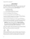
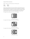
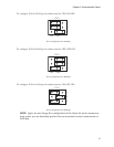
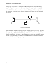
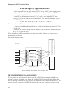
ISACC units are networked by connecting the A terminals together, and the B terminals
together. Next, it is necessary to enable a termination on the two units that are located far-
thest apart. This termination is located at pin header P9, located directly above the RS485
terminal block. To enable termination, move the two black jumpers from the off position to
the on position. If only two ISACC units are being networked, enable both. See the follow-
ing diagram:
node 0
node 1 node 3
node 4
node 2
A
B
A
B
A B
A B A B
Termination
ON
Termination
ON
Five ISACC units networked
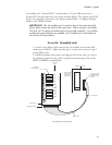
After the units are networked, you must determine the node number for each unit. This must
be done so that the each unit is identified in the network. The “master” unit is identified as 0
(zero). See Chapter 7: PROGRAMMING: “System”, for information on how to program the
network node number. See Chapter 7: PROGRAMMING: “Network” for information on how
to make a network request. See Chapter 8: C PROGRAMMING for information on how to
use network information in C programming.