


34
Sensaphone
®
ISACC Instruction Manual
remove the acrylic panel. Using needlenose pliers, move the shunt to the appropriate position.
See diagrams below. Replace the acrylic panel when finished.
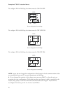
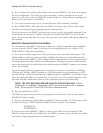
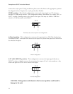
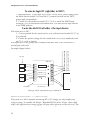
TEMP position - The default configuration connects the input signal to a 5V reference
through a 6.34K pull-up resistor. This configuration allows a thermistor, dry contact (N.C. or
N.O. ), or pulse counting sensor to be wired to the input. You may use either a 2.8K ther-
mistor or a 10K thermistor with ISACC.
P12
TEMP
4-20mA
1
Thermistor, dry contact or pulse count configuration
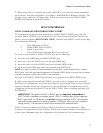
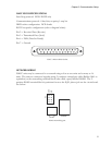
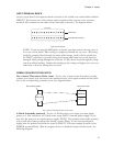
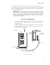
4-20mA position - This configuration connects the input signal to a 249 Ohm load resistor.
This allows ISACC to measure the current at the input. Any sensor that puts out 4-20mA can
be wired to this input.
P12
TEMP
4-20mA
1
4-20mA configuration
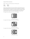
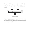
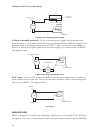
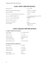
0-5V (NO SHUNT) position - This configuration connects the input signal directly to
ISACC’s analog to digital converter for measuring the output of 0 to 5 volt transducers. Any
sensor that puts out 0-5V can be wired to this input.
P12
TEMP
4-20mA
1
0-5 Volt configuration
CAUTION: Wiring sensors with shunts in the incorrect position could result in
damage to the unit.