


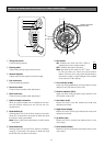
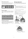

● Power Connection
Use individual power sources for the camera and
optional heater unit.
• Wire colors & functions
-12-
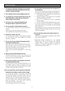
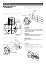
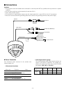
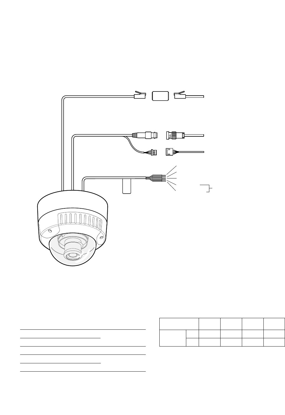
■ Connections
Cautions:
• This product should be installed and connected in conformity with NEC by qualified service personnel or system
installers.
• Do not use a transformer with a capacity of more than 20 V A.
• Use a class 2 power supply.
• To prevent fire or electric shock hazard, use a UL listed cable (VW-1, style 1007) for 24 V AC connections.
• Be sure to connect the GND (grounding) lead of the camera and grounding terminal of the power supply.
Black (Live)
Blue (Neutral)
Green/Yellow (GND)
Brown (Live)
For optional heater
White (Neutral)
BNCBNC
Video output
Control cable
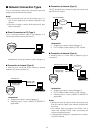
Network
Power 24 V AC
Adapter (supplied)
Adapter
(supplied)
To peripherals
To Video IN (CAMERA IN)
To network
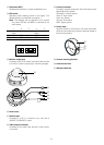
• Cable length and wire gauge
The recommended cable length and thickness are
shown in the table for reference. The voltage sup-
plied to the power terminals of the camera should
be between
19.5 V AC and 28 V AC.
Wire color
White
Brown
Blue
Green/Yellow
Black
Function
24 V AC Live
24 V AC Neutral
GND
24 V AC Live
24 V AC Neutral
Note
For camera
8.6 W
For optional heater
12.1 W
#24
(0.22mm
2
)
Copper wire size
(AWG)
Length
of cable
(approx.)
(m)
(ft)
#22
(0.33mm
2
)
#20
(0.52mm
2
)
#18
(0.83mm
2
)
20 30 45 75
65 100 160 260