


Chapter 6 NI-VXI Configuration Utility
©
National Instruments Corporation 6-15 VXI/VME-PCI8022 for Solaris
before making any NI-VXI function calls or attempting to use the
VXI/VME-MXI-2 Configuration Editor. Refer to the Connect the
MXIbus Cable section at the end of either Chapter 3 or Chapter 4 of
this manual.
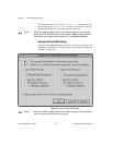
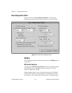
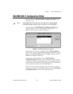
You can select the Yes or No options to manually determine whether the
PCI-MXI-2 should be the MXIbus System Controller. You must still be
certain to cable the MXIbus system appropriately when you make either
of these selections.
Note: Make sure the MXI-2 cable is connected to the PCI-MXI-2 when you
power on or reboot the computer. This is required for the PCI-MXI-2 to
automatically detect whether it will be the MXIbus System Controller.
MXI Bus Timeout
The MXIbus Bus Timeout (BTO) is a watchdog timer for transfers on
the MXIbus. The MXIbus BTO operates only when the PCI-MXI-2 is
acting as the MXIbus System Controller.
After the specified amount of time has elapsed, the BTO circuitry
terminates a MXIbus cycle if no slave has responded. The BTO is also
disabled when the current MXIbus cycle maps to the VXI/VMEbus
through a VXI/VME-MXI-2.
The default timeout value is 1 ms. If the Enable MXI-2 Auto Retry
checkbox option is enabled, you should use a MXI Bus Timeout of
1 ms or greater.
MXI CLK10
The PCI-MXI-2 is capable of either receiving or driving the MXIbus
CLK10 signal.
You can use the Drive or Receive options of the MXI CLK10 feature
to control the direction of the MXIbus CLK10 signal. By default all
MXI-2 boards receive MXI CLK10 (the Receive option is active);
therefore, you must choose one board on your MXI-2 bus to drive
CLK10 by changing the value of the control to Drive. For most
configurations, it is recommended to choose the System Controller as
the CLK10 source for simplicity. The only exception you may want to
make is if you want your triggers synchronous to the VXI 10 MHz
clock.