


Chapter 3 VXI-MXI-2 Configuration and Installation
VXI/VME-PCI8022 for Solaris 3-12
©
National Instruments Corporation
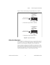
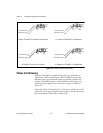
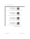
The VXI-MXI-2 can also drive or receive the MXIbus CLK10 signal.
Switch S7 controls whether the VXI-MXI-2 drives MXIbus CLK10
from the VXIbus CLK10 or receives MXIbus CLK10. As shown earlier
in Figure 3-5c, if W3 is configured to use the MXIbus CLK10 to
generate the VXIbus CLK10 signal, switch S7 must be configured to
receive MXIbus CLK10. This is shown again in Figure 3-7a below. If
you change the S7 setting to drive CLK10 out the MXIbus, do not set
the W3 jumper to receive the MXIbus CLK10; instead use the settings
shown in Figure 3-5a or Figure 3-5b as appropriate.
Caution: Do not configure more than one MXIbus device to drive the MXIbus
CLK10. Having a second device driving MXIbus CLK10 could damage the
device.
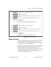
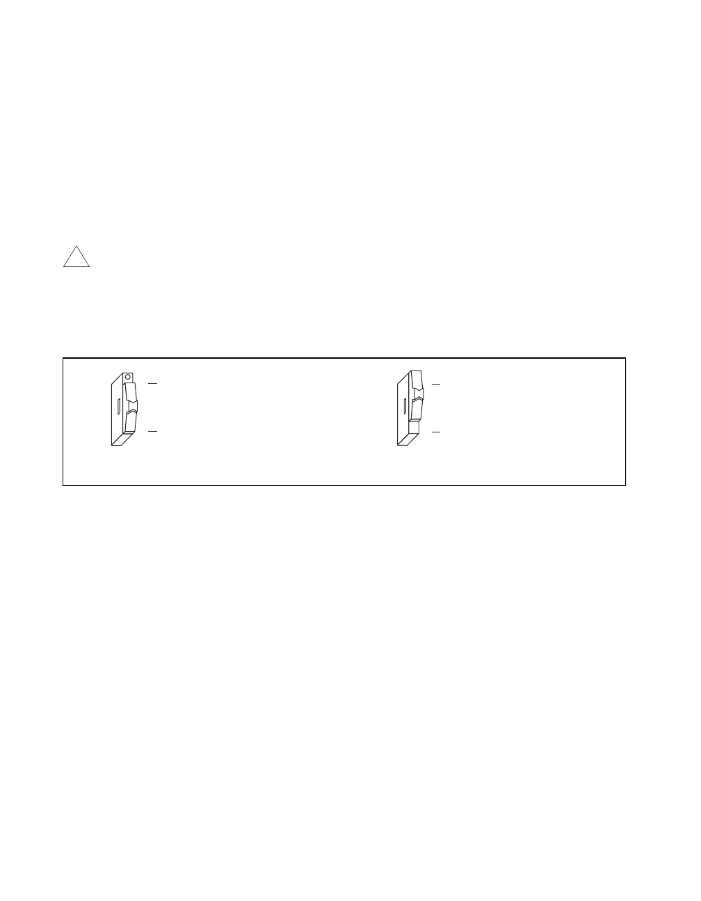
Figure 3-7 shows the configuration settings for receiving and driving
MXIbus CLK10, respectively.
Figure 3-7. Receiving or Driving MXIbus CLK10
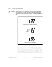
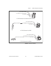
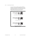
Trigger Input Termination
You can use switch S2 to terminate the external trigger input SMB with
50 Ω. Figure 3-8a shows the default setting for a nonterminated trigger
input SMB. Use the setting of Figure 3-8b to terminate the trigger input
SMB. Switch S2 is located above switches S3, S4, and S5, which have
no effect on this configuration.
!
a
. Receive CLK10 from MXIbus (Default) b. Drive MXIbus CLK10 from VXIbus CLK10
S7
Drive CLK10 out MXIbus
Receive CLK10 from MXIbus
S7
Drive CLK10 out MXIbus
Receive CLK10 from MXIbus