


Chapter 4 VME-MXI-2 Configuration and Installation
©
National Instruments Corporation 4-11 VXI/VME-PCI8022 for Solaris
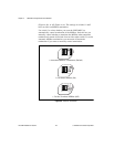
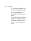
3. Insert the VME-MXI-2 in the slot you have selected by aligning the
top and bottom of the board with the card-edge guides inside the
mainframe. Slowly push the VME-MXI-2 straight into the slot until
its plug connectors are resting on the backplane receptacle
connectors. Using slow, evenly distributed pressure, press the
VME-MXI-2 straight in until it seats in the expansion slot. The
front panel of the VME-MXI-2 should be even with the front panel
of the mainframe.
4. Tighten the retaining screws on the top and bottom edges of the
front panel.
5. Check the installation.
6. Connect the cables as described in the following section before
restoring power.
7. Replace or close any doors or covers to the mainframe.
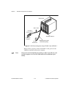
Connect the MXIbus Cable
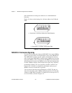
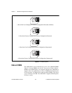
There are two basic types of MXI-2 cables. MXI-2 cables can have
either a single connector on each end or a single connector on one end
and a double connector on the other end.
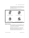
Connect the labeled end of the cable to the MXI-2 device that will be
the MXIbus System Controller. Connect the other end of the cable to the
other device. Be sure to tighten the screw locks to ensure proper pin
connection.
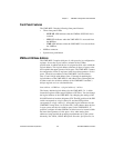
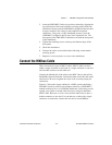
Figure 4-7 shows the correct cabling for a VME system containing a
PCI-MXI-2 board in a PCI-based computer cabled to a VME-MXI-2
module residing in Slot 1 of a VMEbus mainframe. Notice that you can
expand your system to include other devices by using an additional
MXI-2 cable. However, in such a case the first cable needs to have a
double connector on one end. You can then use a cable with a single
connector on each end to connect the last device on the MXIbus.