


©
National Instruments Corporation C-1 VXI/VME-PCI8022 for Solaris
Appendix
C
EEPROM Configuration
This appendix describes how to control the operation of the PCI-MXI-2
onboard EEPROM and how to fix an invalid EEPROM setting.
The EEPROM stores default registers values that are loaded at
power-on. The EEPROM is divided into two halves so that you can
modify one half, while the factory-configured half retains a back-up of
the default user settings.
Controlling the EEPROM Operation
Use switch 1 (FOV) of the four-position switch at location U17 to
control the operation of the EEPROM. Switch 1 determines whether
the PCI-MXI-2 boots off the factory-configured half or the
user-configurable half. In its default setting, the PCI-MXI-2 boots off
the user-configurable half. This switch is useful in the event that the
configuration becomes corrupted in such a way that the PCI-MXI-2
boots to an unusable state.
The TST switch (switch 2 of U17) lets you change the default factory
configuration settings by permitting writes to the factory settings
section of the EEPROM. This switch serves as a safety measure and
should not be needed under normal circumstances. When this switch is
off (its default setting) the factory configuration of the EEPROM is
protected so any writes to the factory area will be ignored. The factory
area is protected regardless of the setting of switch 1 of U17.
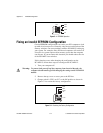
Figure C-1 shows the default settings for EEPROM operation.
Caution:
Do not alter the settings of switches 3 and 4 of U17. Leave these switches
as shown in Figure C-1 unless specifically directed by National
Instruments.
!