


Chapter 3 VXI-MXI-2 Configuration and Installation
©
National Instruments Corporation 3-5 VXI/VME-PCI8022 for Solaris
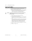
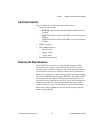
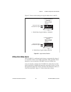
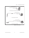
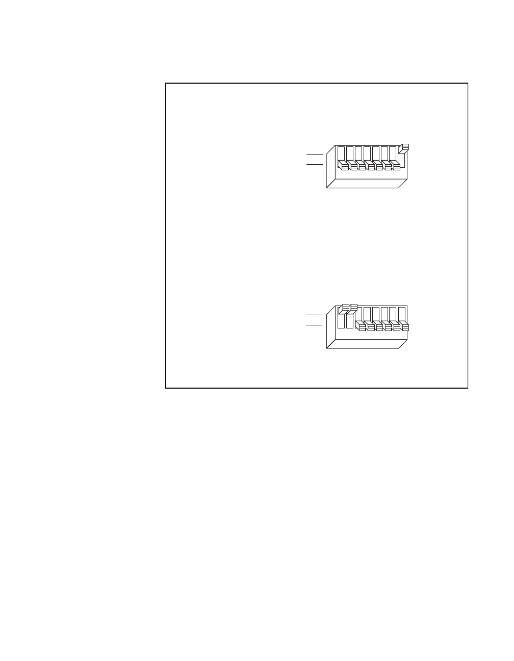
Figure 3-2 shows switch settings for logical address hex 1 and C0.
Figure 3-2. Logical Address Selection
VXIbus Slot 0/Non-Slot 0
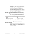
The VXI-MXI-2 is configured at the factory to automatically detect if
it is installed in Slot 0 of a VXIbus mainframe. With automatic Slot 0
detection, you can install the VXI-MXI-2 into any VXIbus slot.
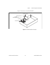
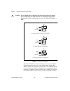
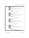
You can manually configure the VXI-MXI-2 for either Slot 0 or Non-
Slot 0 operation by defeating the automatic-detection circuitry. Use the
three-position jumper W2 to select automatic Slot 0 detection, Slot 0, or
Non-Slot 0 operation. Figure 3-3 shows these three settings.
a. Switch Set to Logical Address 1 (Default)
Push up for logic 1
Push down for logic 0
LOGICAL ADDRESS
SWITCH
U43
12345678
Shown at default
setting of Logical
Address 1
b. Switch Set to Logical Address Hex C0
12345678
Push up for logic 1
Push down for logic 0
LOGICAL ADDRESS
SWITCH
U43
Shown at default
setting of Logical
Address 1