


Chapter 3 VXI-MXI-2 Configuration and Installation
VXI/VME-PCI8022 for Solaris 3-2
©
National Instruments Corporation
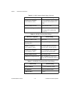
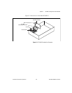
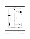
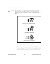
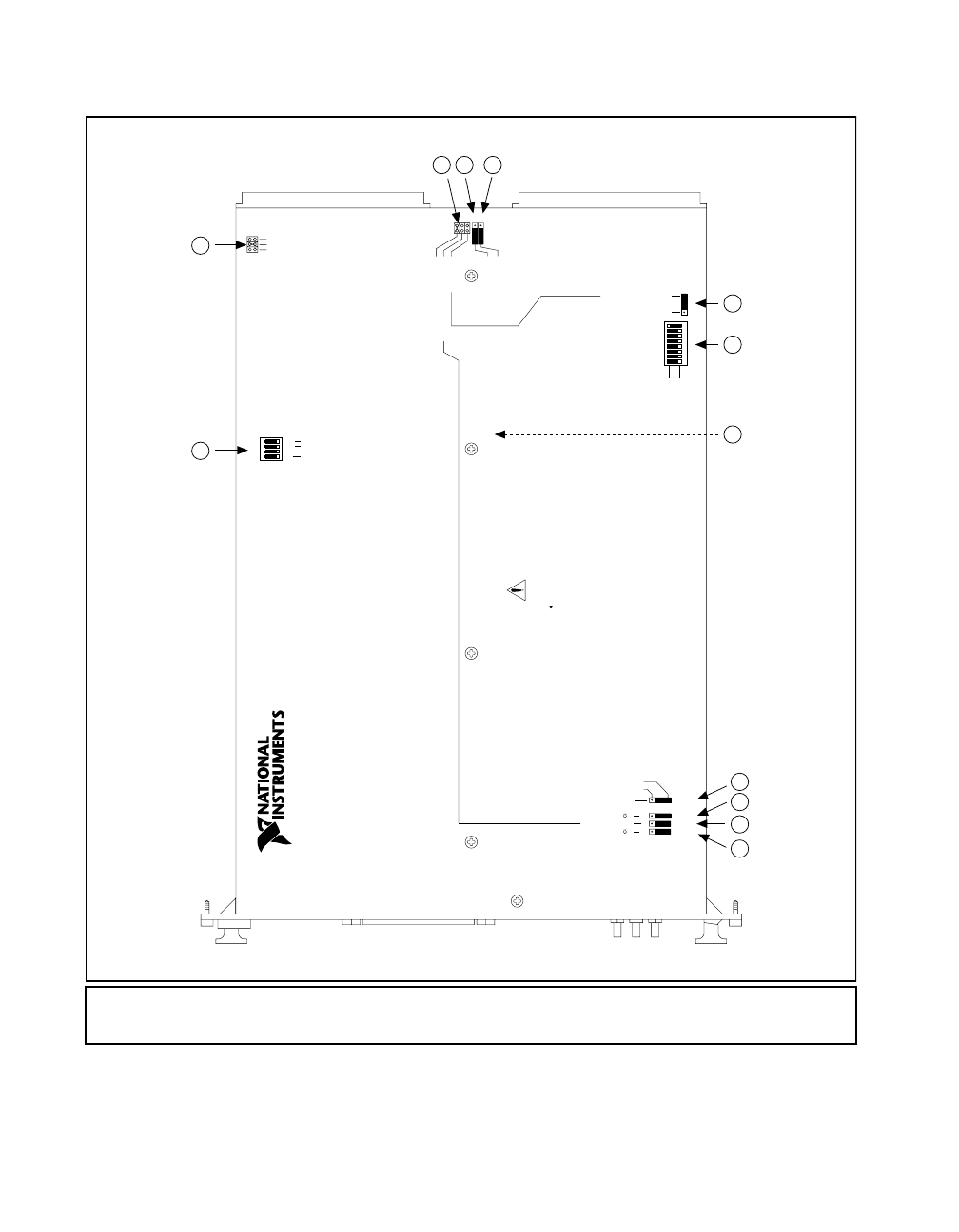
Figure 3-1. VXI-MXI-2 Right-Side Cover
1 U35
2W2
3W3
4S8
5S9
6S7
7 U43
8S6
9S5
10 S4
11 S3
12 S2
(All switches and jumpers shown in default position)
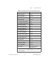
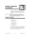
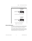
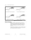
WARNING:
Turn off power to instruments and cables
before installing or removing any modules.
SMB CLK10 Output Polarity (Effective only when S3 is set to "OUT")
50 Termination for SMB CLK10 (Effective only when S3 is set to "IN")
NON-INVERTED
SMB CLK10 Direction
50 Termination for External Trigger Input
S3
S2 Off
Out
S4 Off
S5
In
On
On
INVERTED
VXI-MXI-2
Push up for logic 1
Push down for logic 0
Receive CLK10 from MXIbus
3
Shown at default
LOGICAL ADDRESS
SWITCH
Address 1
setting of Logical
21
Drive CLK10 out MXIbus
654
U43
87
S7
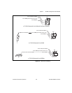
Routing
MXI CLK10
From MXIbus
From SMB (S3 must be set to "IN")
From onboard oscillator
VXI-MXI to left
VXI-MXI to right
Terminate MXIbus
Restore Factory Configuration
Change Factory Configuration
Automatic MXIbus Termination Yes
Yes
No
No
Yes
U35
432
No
Yes
No
1
YesNo
S8
S9
W3
Source
CLK10
Auto
Slot 0
W2
Nonslot 0
1
2
3 4 5
6
7
8
10
9
12
11