


Chapter 3 VXI-MXI-2 Configuration and Installation
©
National Instruments Corporation 3-3 VXI/VME-PCI8022 for Solaris
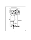
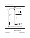
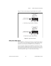
Front Panel Features
The VXI-MXI-2 has the following front panel features.
• Three front panel LEDs
– SYSFAIL LED indicates that the VMEbus SYSFAIL line is
asserted.
– MXI LED indicates when the VXI-MXI-2 is accessed from the
MXIbus.
– VXI LED indicates when the VXI-MXI-2 is accessed from the
VXIbus.
• MXIbus connector
• Three SMB connectors
– External clock
– Trigger output
– Trigger input
• System reset push-button
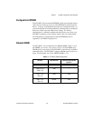
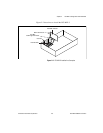
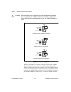
Removing the Metal Enclosure
The VXI-MXI-2 is housed in a metal enclosure to improve EMC
performance and to provide easy handling. Because the enclosure
includes cutouts to facilitate changes to the switch and jumper settings,
it should not be necessary to remove it under normal circumstances.
However, it is necessary to remove the enclosure if you want to change
the amount of DRAM installed on the VXI-MXI-2. Switch S6, which is
directly related to the amount of DRAM you want to install, is also
accessible only by removing the enclosure. If you will be making this
change, remove the four screws on the top, the four screws on the
bottom, and the five screws on the right side cover of the enclosure.
Refer to the Onboard DRAM section later in this chapter for details
about changing DRAM.