


Chapter 4 VME-MXI-2 Configuration and Installation
©
National Instruments Corporation 4-5 VXI/VME-PCI8022 for Solaris
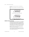
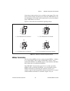
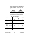
Notice that a fourth position is also available on the jumper. This is the
factory-default setting, which does not connect the VME-MXI-2 to any
user-defined pin. You would use this option only if you are installing a
single VME-MXI-2 in a chassis.
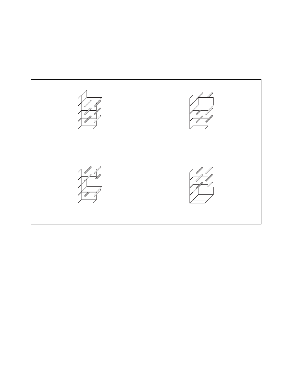
Figure 4-3 shows the four intermodule signaling settings.
Figure 4-3. VME-MXI-2 Intermodule Signaling Settings
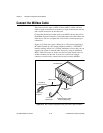
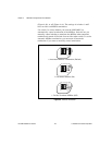
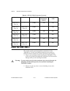
MXIbus Termination
The first and last MXIbus devices connected to the MXIbus—whether
it is a single MXI-2 cable or daisy-chained MXI-2 cables—must
terminate the MXIbus. Any MXIbus devices in the middle of a MXIbus
daisy chain must not terminate the MXIbus.
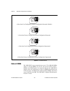
The VME-MXI-2 automatically senses if it is at either end of the
MXIbus cable to terminate the MXIbus. You can manually control
MXIbus termination by defeating the automatic circuitry. Use
switches 3 and 4 of the four-position switch at location U21 to control
whether MXIbus termination is automatic (Figure 4-4a), on
a. User-Defined Pin A5 Selected
W2
A5
C5
C30
NC
b. User-Defined Pin C5 Selected
c. User-Defined Pin C30 Selected
d. No User-Defined Pin Selected (Default)
W2
A5
C5
C30
NC
W2
A5
C5
C30
NC
W2
A5
C5
C30
NC