


42
W415-0788 / A / 09.22.09
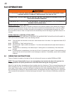
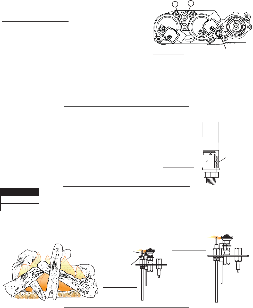
10.0 ADJUSTMENT
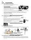
10.1 PILOT BURNER ADJUSTMENT
Adjust the pilot screw to provide properly sized fl ame. Turn in a
clockwise direction to reduce the gas fl ow.
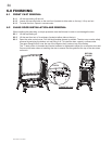
Check Pressure Readings:
Inlet pressure can be checked by turning screw (A) counter-
clockwise 2 or 3 turns and then placing pressure gauge tubing over
the test point. Gauge should read 7” (minimum 4.5”) water column
for natural gas or 13” (11” minimum) water column for propane.
Check that main burner is operating on “HI”.
Outlet pressure can be checked the same as above using screw (B). Gauge should read 3.5” water column fo
r
natural gas or 10” water column for propane. Check that main burner is operating on “HI”.
AFTER TAKING PRESSURE READINGS, BE SURE TO TURN SCREWS CLOCKWISE FIRMLY TO
RESEAL. DO NOT OVERTORQUE.
Leak test with a soap and water solution.
39.4
A
B
PILOT SCREW
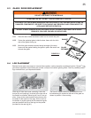
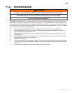
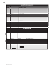
10.2 VENTURI ADJUSTMENT
This model has an air shutter that has been factory set open according to
the chart below:
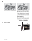
Regardless of venturi orientation, closing the air shutter will cause a more
yellow flame, but can lead to carboning. Opening the air shutter will cause a
more blue flame, but can cause flame lifting from the burner ports. The
flame may not appear yellow immediately; allow 15 to 30 minutes for the
final flame color to be established.
AIR SHUTTER ADJUSTMENT MUST ONLY BE DONE BY A QUALIFIED
INSTALLER!
AIR
SHUTTER
OPENING
VENTURI
BURNER
ORIFICE
49.1
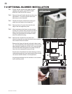
10.4 RESTRICTING VERTICAL VENTS - MODEL GDS60
Vertical installations may display a very active fl ame. If this appearance is not desirable, the vent exit must be re-
stricted using the restrictor vent kit, GDSRP-KT. This will reduce the velocity of the exhaust gases, slowing down
the fl ame pattern and creating a more traditional gentle appearance. Specifi c instructions are included with the kit.
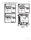
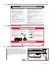
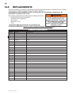
10.3 FLAME CHARACTERISTICS
It’s important to periodically perform a visual check of the pilot and burner fl ames. Compare them to the illustra-
tions provided. If any fl ames appear abnormal call a service person.
3/8” - 1/2”
PILOT
BURNER
FLAME MUST ENVELOP
UPPER 3/8” TO 1/2” OF
FLAME SENSOR
FLAME
SENSOR
ELECTRODE
54.1
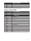
GDS60
NG 3/8”
LP 5/16”
FIGURE 10.1
FIGURE 10.2
FIGURE 10.3a
FIGURE 10.3b