


26
W415-0788 / A / 09.22.09
5.2 WALL AND CEILING PROTECTION
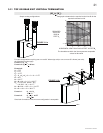
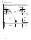
For optimum performance, it is recommended that all horizontal runs have a minimum 1/4" rise per foot when
venting. For safe and proper operation of the appliance, follow the venting instructions exactly.
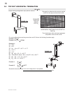
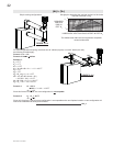
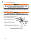
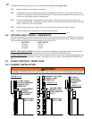
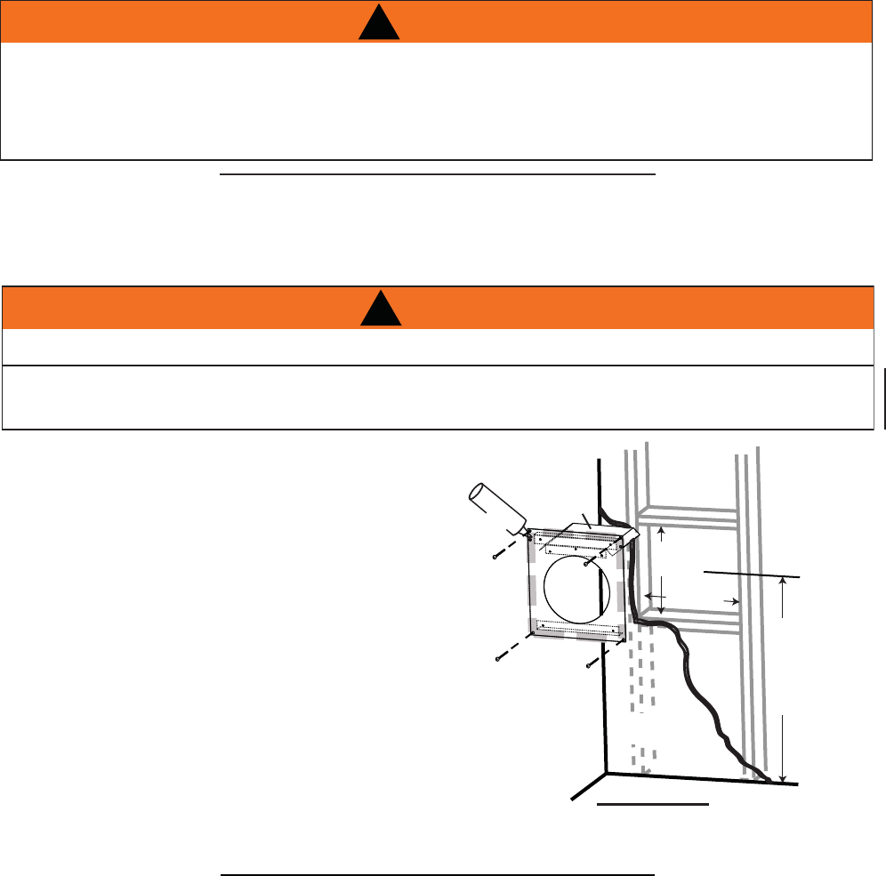
5.2.1 HORIZONTAL INSTALLATION
This application occurs when venting through an exterior wall.
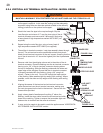
Having determined the correct height for the air terminal
location, cut and frame a hole in the exterior wall as
illustrated to accommodate the fi restop assembly.
Dry fi t the fi restop assembly before proceeding to
ensure the brackets on the rear surface fi t to the
inside surface of the horizontal framing.
The length of the vent shield may be cut shorter
for combustible walls that are less than 8 1/2” thick
but the vent shield must extend the full depth of the
combustible wall.
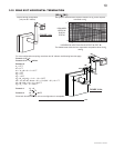
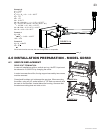
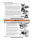
A
. Apply a bead of caulking (not supplied) around the corner edge of
the inside surface of the fi restop assembly, fi t the fi restop
assembly to the hole and secure using the 4 screws W570-0026
(supplied in your manual baggie).
B. Once the vent pipe is installed in its fi nal position, apply high temperature sealant W573-0007 (not
supplied) between the pipe and the fi restop.
DETERMINE
THE
CORRECT
HEIGHT
CAULKING
FIRESTOP
SPACER
VENT
SHIELD
FINISHING
MATERIAL
20.2
!
WARNING
THE FIRESTOP ASSEMBLY MUST BE INSTALLED WITH THE VENT SHIELD TO THE TOP.
TERMINALS MUST NOT BE RECESSED INTO A WALL OR SIDING MORE THAN THE DEPTH OF THE
RETURN FLANGE OF THE MOUNTING PLATE.
10"1/2
9 1/2"
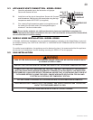
!
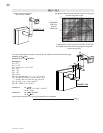
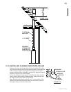
WARNING
DO NOT FILL THE SPACE BETWEEN THE VENT PIPE AND ENCLOSURE WITH ANY TYPE OF
MATERIAL. DO NOT PACK INSULATION OR COMBUSTIBLES BETWEEN CEILING FIRESTOPS.
ALWAYS MAINTAIN SPECIFIED CLEARANCES AROUND VENTING AND FIRESTOP SYSTEMS.
INSTALL WALL SHIELDS AND FIRESTOPS AS SPECIFIED. FAILURE TO KEEP INSULATION OR
OTHER MATERIALS AWAY FROM VENT PIPE MAY CAUSE FIRE.
70.1
FIGURE 5.2.1