31
W415-0788 / A / 09.22.09
5.7.2 INSTALLING "B" VENT
Follow the instructions of the "B" vent manufacturer for chim-
ney installation.
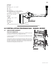
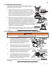
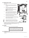
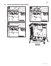
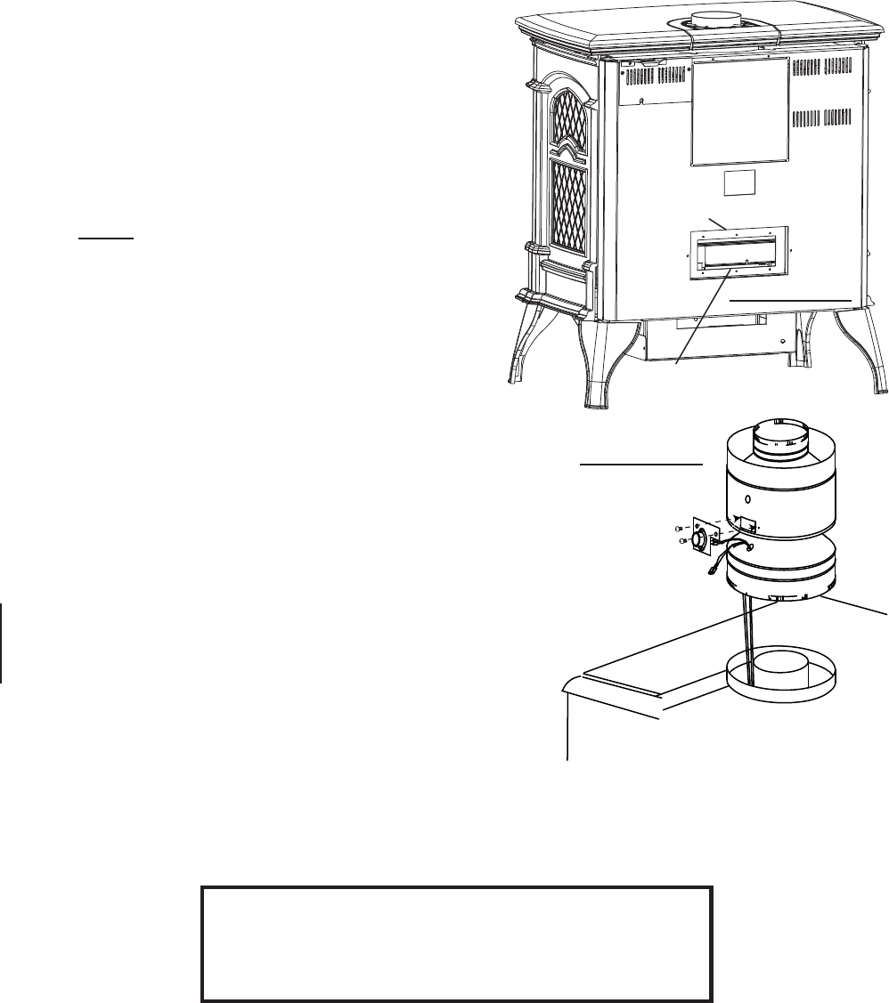
A. Remove the access plate. Remove and discard the
air intake cover plate located directly behind the ac-
cess plate.
B. Feed the 2 wires, supplied, through the 7" collar at the
top of the unit, bring them out the air intake opening
but behind the rear panel as shown.
NOTE: Ensure that 2 female ends remain at the
top. Re-secure the access plate.
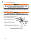
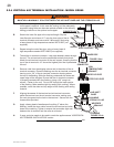
C. Remove the spill switch bracket from the rear of the
adapter. Unscrew the spill switch and discard the
bracket. Attach the spill switch to the bracket supplied
with the appliance and secure onto the adapter.
D. Bring the wires through the lower hole in the adapter.
To pass the wires through the hole more easily, tem-
porarily tape the two terminals together.
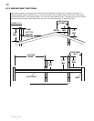
E. With the spill switch opening aligned to the back of the ap-
pliance, take hold of the adapter base and push the crimped
edge into the appliance fl ue collar.
F. Connect the upper wire terminals to the spill switch.
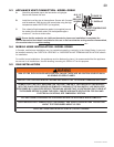
G. Disconnect the wire leads to on/off switch, see "WIRING
DIAGRAM" section and reconnect to the ends of the spill
switch wires. Leave all excess wire in an orderly manner.
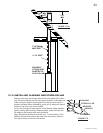
For aesthetics, the adapter has been designed to accept a standard
matte black 7" appliance pipe and the Napoleon® decorative brass
band (standard with the GS-150KT). Both are available from your
local authorized dealer / distributor.
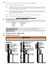
5.7.4 COMBUSTION AIR
This appliance needs air for safe operation and must be installed in such a way that adequate combustion air
is available.
5.7.3 B-VENT
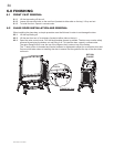
Attach the B-Vent label, shown, in the control area of the appliance.
ATTACH THIS LABEL IN THE CONTROL AREA OF THE FIREPLACE.
THIS FIREPLACE HAS BEEN CONVERTED TO A ‘B’VENT MODEL.
ATTACHEZ CET ETIQUETTE DANS LA REGION DE CONTROLE DU FOYER.
CE FOYER A ETE CONVERTI A UN MODELE A SYSTEME D’EVACUATION ‘B’.
WS-385-160
AIR INTAKE COVER
PLATE LOCATION
ACCESS PLATE
LOCATION
FIGURE 5.7.2a
SPILL
SWITCH
ADAPTER
FIGURE 5.7.2g


