


6
GBDFEINLPGRRUTRCZSVSLHGPO
8. Installation of unit
8.1. Installation
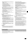
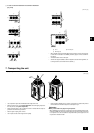
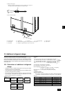
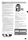
[Fig. 8.1.1]
(Unit: mm [in])
30
[1-3/16]
A
B
C
A Field-supplied M10 anchor bolt B Corner is not seated.
C Fixing bracket for the hole-in anchor bolt (3 locations to fix with screws)
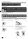
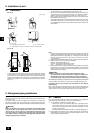
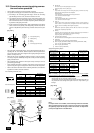
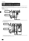
[Fig. 8.1.2]
Outlet
Inlet
InletInlet
H
• In abnormally harsh environments such as clod and/or windy areas, sufficient
countermeasures to guard against excessive wind and snow should be taken
to ensure the unit's correct operation. When the unit is expected to operate in
cooling mode in conditions under 10°C [50°F], in snowy areas, in environments
subject to strong winds or rain, install air inlet and outlet ducting as shown in
[Fig. 8.1.2].
•
Fix unit tightly with bolts so that unit will not fall down due to earthquakes or strong winds.
• Use concrete base or an angle bracket as the foundation of unit.
•
Vibration may be transmitted to the installation section and noise and vibration may
be generated from the floor and walls, depending on the installation conditions.
Therefore, provide ample vibrationproofing (cushion pads, cushion frame, etc.).
• Be sure that the corners are firmly seated. If the corners are not firmly seated,
the installation feet may be bent.
• The projecting length of the anchor bolt should be less than 30 mm [1-3/16 in].
•Post-installed anchor bolts (i.e., bolts not firmly cemented into the base) are
not compatible with this product unless fixing brackets are first mounted on the
four locations.
Note:
1. Height of frame base for snow damage prevention (H) shall be twice as high as
expected snowfall. Width of frame base shall not exceed that of the unit. The
frame base shall be made of angle steel, etc., and designed so that snow and
wind slip through the structure. (If frame base is too wide, snow will be
accumulated on it.)
2.
Install unit so that wind will not directly lash against openings of inlet and outlet ducts.
3. Build frame base at customer referring to this figure.
Material : Galvanized steel plate 1.2T
Painting : Overall painting with polyester powder
Color : Munsell 5Y8/1 (same as that of unit)
4. When the unit is used in a cold region and the heating operation is continuously
performed for a long time when the outside air temperature is below freezing,
install a heater to the unit base or take other appropriate measures to prevent
water from freezing on the base.
Warning:
•
Be sure to install unit in a place strong enough to withstand its weight.
Any lack of strength may cause unit to fall down, resulting in a personal injury.
•
Have installation work in order to protect against strong winds and earthquakes.
Any installation deficiency may cause unit to fall down, resulting in a personal injury.
When building the foundation, give full attention to the floor strength, drain water disposal
<during operation, drain water flows out of the unit>, and piping and wiring routes.
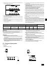
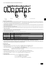
Precautions when routing the pipes and wires below the unit (Without
detachable leg)
When routing the pipes and wires below the unit, be sure that the foundation and
base work do not block the base through-holes. Also make sure the foundation is
at least 100 mm [3-15/16 in] high so that the piping can pass under the unit.
9.1. Caution
This unit uses refrigerant R410A. Follow the local regulations on materials and
pipe thickness when selecting pipes. (Refer to the table on page 7.)
1 Use the following materials for refrigeration piping.
• Material: Use copper alloy seamless pipes made of phosphorus deoxi-
dized copper. Ensure the inner and outer surfaces of the pipes are clean
and free from hazardous sulfur, oxide, dusts, shaving particles, oils, and
moisture (contamination).
•
Size: Refer to item 9.2. for detailed information on refrigerant piping system.
2 Always observe the restrictions on the refrigerant piping (such as rated length,
height difference, and piping diameter) to prevent equipment failure or a de-
cline in heating/cooling performance.
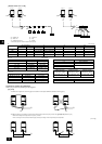
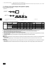
9. Refrigerant piping installation
The pipe is connected via a terminal-branch type connection in which refrigerant
piping from the outdoor unit is branched at the terminal and is connected to each
of the indoor units.
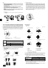
The method of pipe connection is as follows: flare connection for the indoor units,
gas pipes for outdoor units, flare connection for P72 and brazed connection for
P96 ~ P192; liquid pipes, flare connection. Note that the branched sections are brazed.
Warning:
Always use extreme care to prevent the refrigerant gas from leaking while
using fire or flame. If the refrigerant gas comes in to contact with a flame
from any source, such as a gas stove, it breaks down and generates a poi-
sonous gas which can cause gas poisoning. Never weld in an unventilated
room. Always conduct an inspection for gas leakage after installation of the
refrigerant piping has been completed.