


16
GBDFEINLPGRRUTRCZSVSLHGPO
Warning:
• Be sure to use specified wires for connections and ensure no external force is imparted to terminal connections. If connections are not fixed firmly, heating
or fire may result.
• Be sure to use the appropriate type of overcurrent protection switch. Note that generated overcurrent may include some amount of direct current.
Caution:
• Some installation sites may require attachment of a ground leakage breaker for the inverter. If a ground leakage breaker is not installed, there is a danger of
electric shock.
• Do not use anything other than a breaker and fuse with the correct capacity. Using a fuse or wire of too large capacity may cause malfunction or fire.
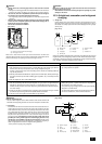
1. Use dedicated power supplies for the outdoor unit and indoor unit. Ensure OC and OS are wired individually.
2. Bear in mind ambient conditions (ambient temperature,direct sunlight, rain water,etc.) when proceeding with the wiring and connections.
3. The wire size is the minimum value for metal conduit wiring. If the voltage drops, use a wire that is one rank thicker in diameter.
Make sure the power-supply voltage does not drop more than 10%.
4. Specific wiring requirements should adhere to the wiring regulations of the region.
5. Power supply cords of parts of appliances for outdoor use shall not be lighter than polychloroprene sheathed flexible cord (design 245 IEC57). For example,
use wiring such as YZW.
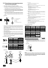
6. A switch with at least 3 mm [1/8 in] contact separation in each pole shall be provided by the Air conditioner installation.
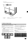
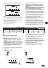
• Remote controller cable length: r
1, r2
=
10 m [32 ft] (0.3 to 1.25 mm
2
[AWG 22 to 16])
If the length exceeds 10 m [32 ft], use 1.25 mm
2
[AWG 16] shielded cable and calculate the length of that portion (L4 and L7) as within
the total extended length and the longest remote length.
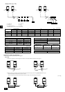
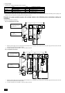
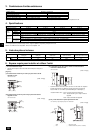
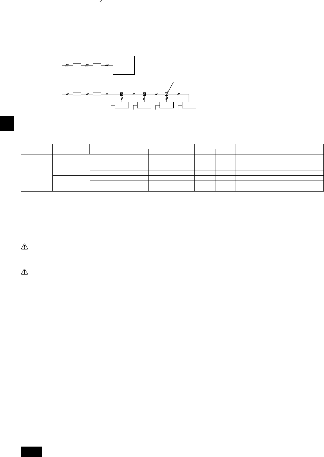
11.4. Wiring of main power supply and equipment capacity
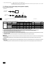
Schematic Drawing of Wiring (Example)
[Fig. 11.4.1]
BA
C
3~208–230V
L
1
, L
2
, L
3
BA
~208–230V
L, N
Ground
Ground Ground Ground Ground
E E
D
EE
A Switch (Breakers for wiring and current leakage) B Breakers for current leakage C Outdoor unit
D Pull box E Indoor unit
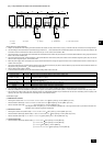
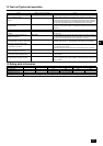
Thickness of wire for main power supply, on/off capacities
44.1
59.7
44.1
44.1
59.7
59.7
-
60
75
60
60
75
75
15
60
75
60
60
75
75
15
13.3 [6]
21.2 [4]
13.3 [6]
13.3 [6]
21.2 [4]
21.2 [4]
0.41 [22]
13.3 [6]
21.2 [4]
13.3 [6]
13.3 [6]
21.2 [4]
21.2 [4]
0.41 [22]
Main cable
Swtich (A)
Minimum wire thickness (mm
2
[AWG]
)
Branch Capacity Fuse
Outdoor unit
-
-
-
-
-
-
0.41 [22]
Breaker for wiring
(NFB)(A)
Ground
PUHY-HP72THMU-A
PUHY-HP96THMU-A
PUHY-HP144TSHMU-A
PUHY-HP72THMU-A
PUHY-HP72THMU-A
PUHY-HP192TSHMU-A
PUHY-HP96THMU-A
PUHY-HP96THMU-A
Model Unit combination
60A 100mA 0.1sec. or less
75A 100mA 0.1sec. or less
60A 100mA 0.1sec. or less
60A 100mA 0.1sec. or less
75A 100mA 0.1sec. or less
75A 100mA 0.1sec. or less
20A 30mmA 0.1sec. or less
Breaker for current leakage
Maximum
current (A)
60
75
60
60
75
75
15
Indoor unit