


11
GBDFEINLPGRRUTRCZSVSLHGPO
Caution:
•Always remove the connecting pipe from the valve and braze it outside
the unit.
-Brazing the connecting pipe while it is installed will heat the valve and cause
trouble or gas leakage. The piping, etc. inside the unit may also be burned.
• Use ester oil, ether oil or alkylbenzene (small amount) as the refrigerat-
ing machine oil to coat flares and flange connections.
- The refrigerating machine oil will degrade if it is mixed with a large amount of
mineral oil.
•Keep the valve closed until refrigerant charging to the pipes to be added
on site has been completed. Opening the valve before charging the re-
frigerant may result in unit damage.
• Do not use a leak detection additive.
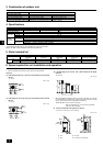
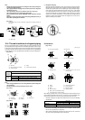
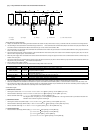
[Fig. 10.2.4]
A
B
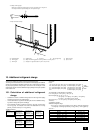
A Example of closure materials (field supply)
B Fill the gap at the site
Make sure to seal-off and excess space around areas where the wires and
refrigerant pipes enter the unit to ensure that small animals and rainwater cannot
enter the unit through such openings and cause damage to the unit.
Caution:
Make sure to seal-off and excess space around areas where the wires and
refrigerant pipes enter the unit.
• Small animals and rainwater entering through the openings may cause
damage to the device.
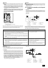
10.3. Airtight test, evacuation, and refrigerant
charging
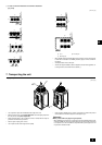
1 Airtight test
Perform with the valve of the outdoor unit closed, and pressurize the connec-
tion piping and the indoor unit from the service port provided on the valve of
the outdoor unit. (Always pressurize from both the liquid pipe and the gas pipe
service ports.)
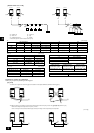
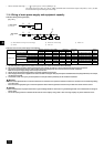
[Fig. 10.3.1]
D
C
C
B
B
E
F
G
H
I
J
A
LO
HI
A Nitrogen gas B To indoor unit C System analyzer
D Lo knob E Hi knob F Valve
G Liquid pipe H Gas pipe I Outdoor unit
J Service port
Observe the following restrictions when conducting an air tightness test to prevent
negative effects on the refrigerating machine oil. Also, with nonazeotropic refriger-
ant (R410A), gas leakage causes the composition to change and affects perform-
ance. Therefore, perform the airtightness test cautiously.
Restriction
• If a flammable gas or air (oxygen) is used as the pressurization
gas, it may catch fire or explode.
• Do not use a refrigerant other than that indicated on the unit.
• Sealing with gas from a cylinder will cause the composition of
the refrigerant in the cylinder to change.
• Use a pressure gauge, charging hose, and other parts especially
designed for use with R410A.
• An electric leak detector for R22 cannot detect leaks of R410A.
• Do not use a haloid torch. (Leaks cannot be detected.)
Airtight test procedure
1. Nitrogen gas pressurization
(1) After pressurizing to the design pressure (4.15 MPa [602 psi]) using nitrogen gas, allow it to
stand for about one day. If the pressure does not drop, airtightness is good.
However, if the pressure drops, since the leaking point is unknown, the following bubble test
may also be performed.
(2) After the pressurization described above, spray the flare connection parts, brazed parts, flanges,
and other parts that may leak with a bubbling agent (Kyuboflex, etc.) and visually check for
bubbles.
(3) After the airtight test, wipe off the bubbling agent.
2. Pressurization using refrigeration gas and nitrogen gas
(1) After first pressurizing with R410A liquid refrigerant to a gas pressure of approximately 0.2
Mpa [29 psi], pressurize to the design pressure of 4.15 Mpa [602 psi] using nitrogen gas.
However, do not pressurize at one time. Stop during pressurization and check that the pres-
sure does not drop.
(2) Check for gas leaks by checking the flare connection parts, brazed parts, flanges, and other
parts which may leak using an R410A compatible electric leak detector.
(3) This test may be used together the with bubble type gas leak test.
Caution:
Only use refrigerant R410A.
- The use of other refrigerant such as R22 or R407C, which contains chlorine, will
deteriorate the refrigerating machine oil or cause the compressor to malfunction.
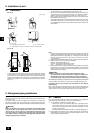
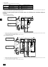
2 Evacuation
Evacuate with the valve of the outdoor unit closed and evacuate both the con-
nection piping and the indoor unit from the service port provided on the valve
of the outdoor unit using a vacuum pump. (Always evacuate from the service
port of both liquid pipe and gas pipe.) After the vacuum reaches 650 Pa [abs]
[0.0943 psi/5 Torr], continue evacuation for at least one hour or more. Then,
stop the vacuum pump and leave it for 1 hour. Ensure the degree of vacuum
has not increased. (If the degree of vacuum increase is larger than 130 Pa
[0.01886 psi/1.0 Torr], water might have entered. Apply pressure to dry
nitrogen gas up to 0.05 MPa [7.25 psi] and vacuum again.) Finally, seal in
with the liquid refrigerant through the liquid pipe, and adjust the gas piping to
obtain an appropriate amount of the refrigerant during operation.
* Never perform air purging using refrigerant.
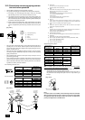
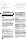
[Fig. 10.3.2]
LO
HI
B
A
K
J
L
H
M
C
D
EN
N
O
F
G
I
A System analyzer B Lo knob C Hi knob
D Valve E Liquid pipe F Gas pipe
G Service port H Three-way joint I Valve
J Valve K R410A cylinder L Scale
M Vacuum pump N To indoor unit O Outdoor unit