


14
GBDFEINLPGRRUTRCZSVSLHGPO
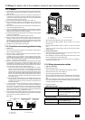
Example of a group operation system with multiple outdoor units (Shielding wires and address setting are
necessary.)
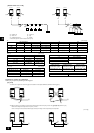
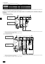
<Examples of transmission cable wiring>
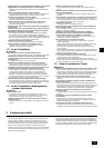
[Fig. 11.3.1] M-NET Remote Controller
A BC
E
D
M1M2
M1M2
S
TB7
TB3
IC
(51)
M1 M2 S
TB5
ME
(01)
IC
M1 M2 S
TB5
(02)
IC
M1 M2 S
TB5
(04)
IC
M1 M2 S
TB5
(03)
IC
M1 M2 S
TB5
(05)
IC
M1 M2 S
TB5
(07)
IC
M1 M2 S
TB5
(06)
L2
L1
(101)
ME
(105)
ME
(103)
ME
(155)
OC
M1M2
M1M2
S
TB7
TB3
(52)
OC
r3
ABS
System
controller
L3
L6
L4
L5
r2
r4
r1
A B A BAB
A
B
CN41
CN41
CN40
*1: When the power supply unit is not connected to the transmission line for centralized control, disconnect the male power supply connector (CN41) from ONE
outdoor unit in the system and connect it to CN40.
*2: If a system controller is used, set SW2-1 on all of the outdoor units to ON.
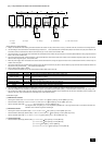
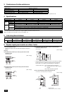
[Fig. 11.3.2] MA Remote Controller
A B C
E
D
M1 M2
M1M2
S
TB7
TB3
M1 M2
12S
TB5
TB15
12
TB15
12
TB15
12
TB15
12
TB15
12
TB15
12
TB15
MA
M1 M2 S
TB5
M1 M2 S
TB5
M1 M2 S
TB5
M1 M2 S
TB5
M1 M2 S
TB5
M1 M2 S
TB5
M1M2
M1 M2 S
TB7
TB3
c1
c4
AB
AB
AB
AB
ABS
c1
c1
c2
CN41
CN40
CN41
IC
(51)
(01)
IC
(02)
IC
(04)
IC
(03)
IC
(05)
IC
(07)
IC
(06)
MA
MA
MA
(52)
OC
System
controller
OC
L2
L6
L3 L4
L1
c3
c2
c2
*1: When the power supply unit is not connected to the transmission line for centralized control, disconnect the male power supply connector (CN41) from ONE
outdoor unit in the system and connect it to CN40.
*2: If a system controller is used, set SW2-1 on all of the outdoor units to ON.
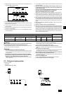
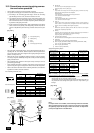
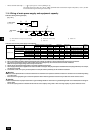
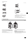
2 Wiring examples
• Controller name, symbol and allowable number of controllers.
Name Code Possible unit connections
Outdoor unit
Indoor unit
Remote controller
Other
Main unit
Sub unit
Indoor unit controller
Remote controller (*1)
Transmission booster unit
– (*2)
– (*2)
1 to 32 units per 1 OC (*1)
2 units maximum per group
0 to 1 unit per 1 OC (*1)
OC
OS
IC
RC
RP
*1 A transmission booster (RP) may be required depending on the number of connected indoor unit controllers.
*2 OC and OS of the outdoor units in the same refrigerant system are automatically identified. They are identified as OC and OS in descending order of capacity. (If the
capacity is the same, they will be in ascending order of their address number.)
<A> Change the jumper connec-
tor from CN41 to CN40 *1
<B> SW2-1:ON *2
<C> Keep the jumper connector
on CN41
<B> SW2-1:ON *2
<A> Change the jumper connec-
tor from CN41 to CN40 *1
<B> SW2-1:ON *2
<C> Keep the jumper connector
on CN41
<B> SW2-1:ON *2