


12
GBDFEINLPGRRUTRCZSVSLHGPO
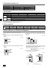
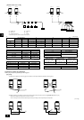
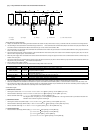
Penetrations
[Fig. 10.4.4]
(Unit: mm [in])
<A> Inner wall (concealed) <B> Outer wall
A B
A B
D
C
<C> Outer wall (exposed) <D> Floor (waterproofing)
E
I
B
D
F
G
B
<E> Roof pipe shaft <F> Penetrating portion on fire limit and
boundary wall
F
H
D
B
G
I
A
J
10001000
[39-3/8] [39-3/8]
A Sleeve B Heat insulating material
C Lagging D Caulking material
E Band F Waterproofing laye
G Sleeve with edge H Lagging material
I Mortar or other incombustible caulking
J Incombustible heat insulation material
When filling a gap with mortar, cover the penetration part with steel plate so that
the insulation material will not be caved in. For this part, use incombustible mate-
rials for both insulation and covering. (Vinyl covering should not be used.)
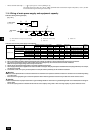
• Insulation materials for the pipes to be added on site must meet the following
specifications:
* Installation of pipes in a high-temperature high-humidity environment, such as
the top floor of a building, may require the use of insulation materials thicker
than the ones specified in the chart above.
* When certain specifications presented by the client must be met, ensure that
they also meet the specifications on the chart above.
Note:
•Always add an appropriate amount of refrigerant. Also always charge the
system with liquid refrigerant.
• Use a gauge manifold, charging hose, and other parts for the refrigerant
indicated on the unit.
• Use a graviometer. (One that can measure down to 0.1 kg [3 oz].)
• Use a vacuum pump with a reverse flow check valve.
(Recommended vacuum gauge: ROBINAIR 14830A Thermistor Vacuum
Gauge)
Also use a vacuum gauge that reaches 65 Pa [abs] [0.0943 psi/0.5 Torr] or
below after operating for five minutes.
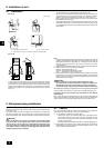
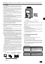
3 Refrigerant Charging
Since the refrigerant used with the unit is nonazerotropic, it must be charged in
the liquid state. Consequently, when charging the unit with refrigerant from a
cylinder, if the cylinder does not have a siphon pipe, charge the liquid refriger-
ant by turning the cylinder upside-down as shown in Fig.10.3.3. If the cylinder
has a siphon pipe like that shown in the picture on the right, the liquid refriger-
ant can be charged with the cylinder standing upright. Therefore, give careful
attention to the cylinder specifications. If the unit should be charged with gas
refrigerant, replace all the refrigerant with new refrigerant. Do not use the re-
frigerant remaining in the cylinder.
[Fig. 10.3.3]
<If the cylinder does not have a siphon pipe, charge with the refrigerant cylinder up-
side-down.>
A Siphon pipe
A
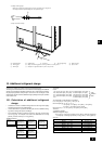
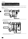
10.4. Thermal insulation of refrigerant piping
Be sure to add insulation work to refrigerant piping by covering liquid pipe and gas
pipe separately with enough thickness heat-resistant polyethylene, so that no gap
is observed in the joint between indoor unit and insulating material, and insulating
materials themselves. When insulation work is insufficient, there is a possibility of
condensation drip, etc. Pay special attention to insulation work in the ceiling plenum.
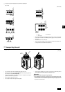
[Fig. 10.4.1]
C
A
B
D
E
A Steel wire B Piping
C Oily mastic asphalt or asphalt D Heat insulation material A
E Outer covering B
Note:
• When using polyethylene cover as covering material, asphalt roofing shall
not be required.
• No heat insulation must be provided for electric wires.
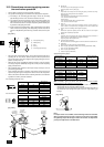
[Fig. 10.4.2]
B
A
D
C
E
E
E
D
A
B
A Liquid pipe B Gas pipe C Electric wire
D Finishing tape E Insulator
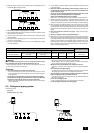
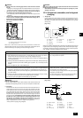
[Fig. 10.4.3]
Heat
insulation
material A
Outer
covering B
Glass fiber + Steel wire
Adhesive + Heat - resistant polyethylene foam + Adhesive tape
Indoor Vinyl tape
Floor exposed Water-proof hemp cloth + Bronze asphalt
Outdoor Water-proof hemp cloth + Zinc plate + Oily paint
Thickness
Temperature Resistance
Pipe size
ø
6.35 to 25.4 mm [1/4 to 1 in]
10 mm min. [13/32 in min.]
100°C min.
[212
°F
min.]
ø
28.58 to 41.28 mm [1-1/8 to 1-21/32 in]
15 mm min. [19/32 in min.]