


82
OPERATING PROCEDURE PHOTOS
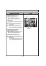
Photo 4
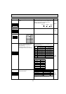
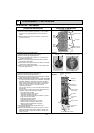
4. Removing the thermistor <Outdoor 2-phase pipe> (TH6)
(1) Remove the service panel. (See Figure 1)
(2) Remove the top panel. (See Figure 1)
(3) Disconnect the connectors, TH6 and TH7 (red), on the
controller circuit board in the electrical parts box.
(4) Loosen the clamp for the lead wire in the rear of the
electrical parts box.
(5) Pull out the thermistor <Outdoor 2-phase pipe> (TH6)
from the sensor holder.
Note: In case of replacing thermistor <Outdoor 2-phase pipe>
(TH6), replace it together with thermistor <Outdoor>
(TH7) since they are combined together. Refer to No.5
below to remove thermistor <Outdoor>.
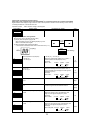
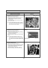
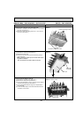
5. Removing the thermistor <Outdoor> (TH7)
(1) Remove the service panel. (See Figure 1)
(2) Remove the top panel. (See Figure 1)
(3) Disconnect the connector TH7 (red) on the controller cir-
cuit board in the electrical parts box.
(4) Loosen the clamp for the lead wire in the rear of the elec-
trical parts box. (See Photo 4)
(5) Pull out the thermistor <Outdoor> (TH7) from the sensor
holder.
Note: In case of replacing thermistor <Outdoor> (TH7),
replace it together with thermistor <Outdoor 2-phase
pipe> (TH6), since they are combined together. Refer
to No.4 above to remove thermistor <Outdoor 2-phase
pipe>.
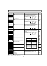
Photo 6
Clamp
Controller circuit board (C.B.)
Thermistor
<Outdoor 2-phase pipe>
(TH6)
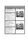
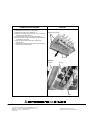
6. Removing the thermistor <Outdoor pipe> (TH3) and
thermistor <Discharge> (TH4)
(1) Remove the service panel. (See Figure 1)
(2) Disconnect the connectors, TH3 (white) and TH4 (white),
on the controller circuit board in the electrical parts box.
(3) Loosen the clamp for the lead wire in the rear of the
electrical parts box. (See Photo 4)
(4) Pull out the thermistor <Outdoor pipe> (TH3) and
thermistor <Discharge> (TH4) from the sensor holder.
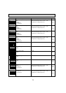
Photo 5
Thermistor <Discharge> (TH4)
Thermistor <Outdoor pipe> (TH3)
Compressor (MC)
Lead wire of thermistor
<Outdoor> (TH7)
Sensor holder