


38
A
A
A
BB
BBB
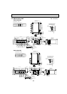
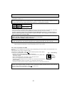
2 branches pipe (joint)
: optional parts
Branch box #1
Branch box #2
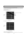
■ In case of using 2-branch boxes
A
BB BBB
Branch box
7
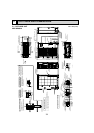
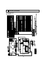
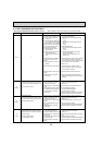
NECESSARY CONDITIONS FOR SYSTEM CONSTRUCTION
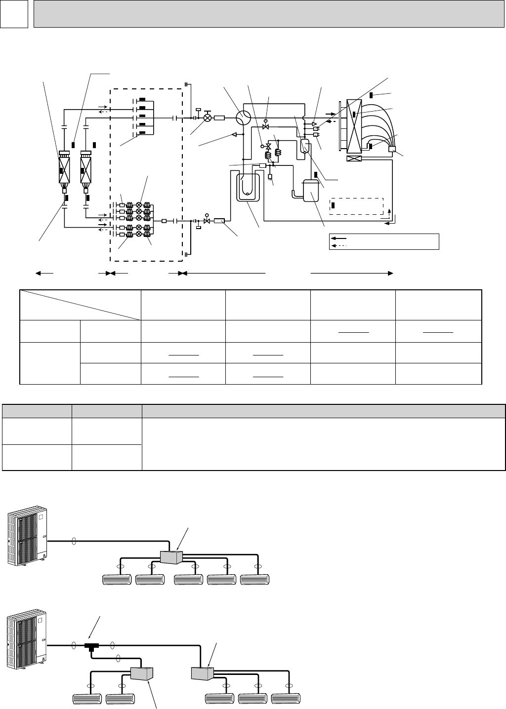
REFRIGERANT SYSTEM DIAGRAM MXZ-8B48NA
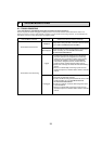
Piping connection size
Thermistor TH6
(Pipe temperature : condenser)
Thermistor TH7
(Outdoor temperature)
Thermistor TH3
(Pipe temperature : liquid)
Strainer
#100
Strainer
#100
Oil separator
Low
pressure
switch
63L
High
pressure
switch
63H
Compressor
Thermistor TH4
(Discharge temperature)
Thermistor TH8
(Fin temperature)
Strainer
#100
Strainer
#50
Check valve
(High Pressure)
Check valve
(Low Pressure)
Capillary
tube3
Capillary
tube4
Capillary
tube2
Capillary
tube1
E
D
C
B
A
Strainer
#100
Condenser / evaporator
temperature thermistor
(TH5 or RT12)
Pipe temperature
thermistor / liquid
(TH2 or RT13)
Strainer
#100
Indoor units Branch box Outdoor unit
Thermistor (TH-A~E)
(Gas pipe temperature)
LEV A~E
(Linear expansion valve)
Room temperature
thermistor (TH1 or RT11)
Service port
Service port
Ball valve
Stop valve
Bypass valve(SV2)
Bypass valve (SV1)
High pressure sensor
discharge pressure sensor
63HS
Accumulator
4-way valve
Distributor
with Strainer
Refrigerant flow in cooling
Refrigerant flow in heating
Outdoor unit
MXZ-8B48NA
PAC-AKA51BC
PAC-AKA31BC
Branch box
Capillary tube 1
(For return of oil
from oil separator)
Capillary tube 2
(For SV2)
Capillary tube 3
ahead of LEV
(in cooling mode)
Capillary tube 4
behind LEV
(in cooling mode)
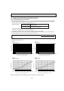
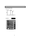
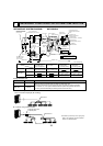
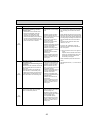
:2.5 % :0.8 % L1000
(:0.098 % :0.031 % L(39-1/2))
:4 % :2.4 % L250
(:0.157 % :0.094 % L10)
(:4 % :2.4 % L140) % 5
(:0.157 % :0.094 % L(5-1/2)) % 5
(:4 % :2.2 % L130) % 5
(:0.157 % :0.087 % L(5-1/8)) % 5
(:4 % :2.4 % L140) % 3
(:0.157 % :0.094 % L(5-1/2)) % 3
(:4 % :2.2 % L130) % 3
(:0.157 % :0.087 % L(5-1/8)) % 3
unit : mm (inch)
■ In case of using 1-branch box
Flare connection employed (No. brazing)
A
B
Liquid (mm)
{9.52
Gas (mm)
{15.88
The pipe connection size differs according to the type and capacity of indoor units.
Match the piping connection size of branch box with indoor unit.
If the piping connection size of branch box does not match the piping connection
size of indoor unit, use optional different-diameter (deformed) joints to the branch
box side. (Connect deformed joint directly to the branch box side.)
■ installation procedure (2 branch pipe (joint))
Refer to the installation manuals of MSDD-
50AR-E and MSDD-50BR-E.