


48
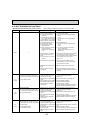
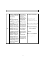
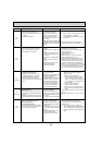
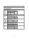
Error Code
Abnormal point and detection method
Judgment and action
Case
E0
(No display)
Remote controller communication
error (Signal receiving error)
(1) Abnormal if any signal from IC of
refrigerant address “0” could not be
normally received for 3 minutes.
(2) Abnormal if sub remote controller
could not receive any signal for 2 min-
utes.
1 Defective communication circuit
of remote controller
2 Defective communication circuit
of indoor controller board of
refrigerant address “0”
3 Noise has entered into transmis-
sion line of remote controller.
4 All remote controllers are set
as “sub” remote controller. In
this case, E4 is displayed at
outdoor LED, and E0 is dis-
played at remote controller.
1~3 Diagnose remote controller.
Take actions as follows according to
diagnosis result.
a) When “RC OK” is displayed,
remote controllers have no problem.
Turn the power off, and on again to
check. If, “PLEASE WAIT” is displayed
for 4 minutes or more, replace indoor
controller board.
b) When “RC NG” is displayed,
replace remote controller.
c) When “RC E3” or “ERC 00-66” is dis-
played, noise may be causing abnor-
mality.
4 Set a remote controller to main, and the other
to sub.
w The descriptions above, 1-3, are for E0 and
E3.
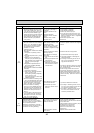
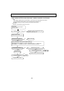
E3
(No display)
Remote controller communication error
(Transmitting error)
(1) Abnormal if sub remote controller could
not find blank of transmission path for 6
seconds.
(2) Abnormal if remote controller could not
finish transmitting 30 times continuously.
1 Defective communication circuit
of remote controller
2 Noise has entered into trans-
mission line of remote controller.
3 Two remote controllers are set
as "main."
(In case of 2 remote controllers)
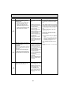
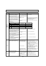
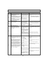
E8
(6840)
Indoor - branch box/branch box -
outdoor unit communication error
(Signal receiving error)
(Branch box/outdoor unit)
(1) Abnormal if branch box/outdoor control-
ler circuit board could not receive any-
thing normally for 3 minutes.
1 Contact failure of indoor/out-
door unit connecting wire
2 Defective communication circuit
of branch box/outdoor controller
circuit board
3 Defective communication circuit
of indoor/branch box controller
board
4 Noise has entered into indoor–
branch box/branch box–
outdoor unit connecting wire.
1 Check disconnection or looseness of indoor–
branch box/branch box –outdoor unit
connecting wire of indoor or branch box or
outdoor units.
2~4 Turn the power off, and on again to
check. Replace indoor controller board or
branch controller board or outdoor control-
ler circuit board if abnormality is displayed
again.
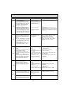
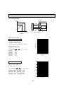
UL
(1300)
Low pressure (63L operated)
Abnormal if 63L is operated (under
–0.03MPa [–4.35PSIG]) during compres-
sor operation.
63L: Low-pressure switch
1 Stop valve of outdoor unit is
closed during operation.
2 Disconnection or loose con-
nection of connector (63L) on
outdoor controller board
3 Disconnection or loose connec-
tion of 63L
4 Defective outdoor controller board
5 Leakage or shortage of refrigerant
6 Malfunction of linear expansion
valve
1 Check stop valve.
2~4 Turn the power off and on again to check
if F3 is displayed on restarting.
If F3 is displayed, follow the F3 process-
ing direction.
5 Correct to proper amount of refrigerant.
6 Check linear expansion valve. Refer to 8-6.
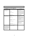
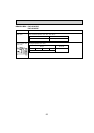
UP
(4210)
Compressor overcurrent interruption
Abnormal if overcurrent DC bus or com-
pressor is detected after compressor
starts operating for 30 seconds.
1 Stop valve of outdoor unit is
closed.
2 Decrease of power supply volt-
age
3 Looseness, disconnection or
converse of compressor wiring
connection
4 Defective fan of indoor/outdoor
units
5 Short cycle of indoor/outdoor
units
6 Defective input circuit of out-
door controller board
7 Defective compressor
1 Open stop valve.
2 Check facility of power supply.
3 Correct the wiring (U·V·W phase) to com-
pressor. Refer to 8-7.
4 Check indoor/outdoor fan.
5 Solve short cycle.
6 Replace outdoor controller circuit board.
7 Check compressor. Refer to 8-6.
W
Before the replacement of the outdoor con-
troller circuit board, disconnect the wiring for
compressor from the outdoor power circuit
board and check the output voltage among
phases, U, V, W, during test run. No defect on
board if voltage among phases (U-V, V-W and
W-U) is same. Make sure to perform the volt-
age check with same performing frequency.