


59
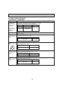
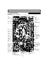
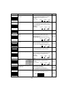
Communication power supply
D71 Voltage
24V DC
CNS
S1-S2: 208/230V AC
(Branch box/outdoor
unit connecting wire)
CNAC
2 to 4: Power supply for
outdoor controller circuit
board (208/230V AC)
1 to 3: Power supply for
indoor and outdoor unit
connection wire
(208/230V AC)
CNF1, CNF2
Connect to the fan motor
1-4: 280-350V DC
5-4: 15V DC
6-4: 0-6.5V DC
7-4: 15V DC(When stopped)
7.5V DC(When operated)(0V-15V pulse)
21S4
4-way valve
63H
High pressure
switch
SV1
Solenoid valve 1
CN4
Transmission to out-
door power circuit
board (CN4)
SW4
Test operation
SW6
Model select
SW5
Function switch
SW1
Forced defrost, detect history record reset
CNDM
1 to 2:
Input of low noise
mode
1 to 3:
Input of external con-
tact point
TH4
Thermistor
<Discharge>
TH3
Thermistor
<Outdoor pipe>
TH7/6
Thermistor
<Outdoor/
2-phase pipe>
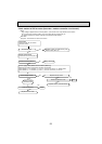
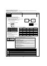
CNDC
280-350V DC (1+, 3-)
Connect to outdoor power circuit
board(CNDC)
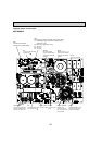
+ -
V
FG
(TEST POINT 4)
(Voltage between
right pins of PC5C
and PC5D, pin 3
and pin 4)
(Same as
(CNF1
7(+)-4(-))
VSP
(TEST POINT 3)
(Voltage between pins
of C5A, C5B): DC 0V
(when stopped), DC 1–
6.5V
(when operated)
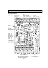
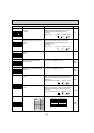
SW7
CN51
SW8
CN2
Connect to the outdoor
power circuit board (CN2)
1-5: Reception from
power circuit board
2-5: Zero cross signal
(0-5V DC)
3,4: Not used
6-5: 16V DC
7-5: 16V DC
CN52C
(Connect to the power
circuit board (CN52C))
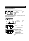
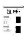
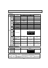
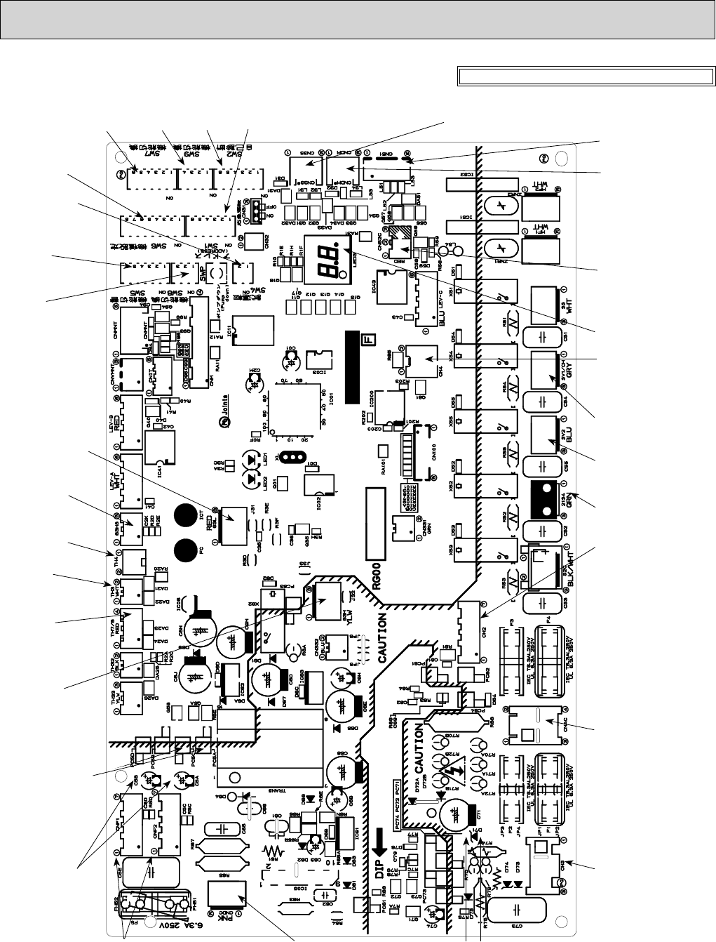
8-7. TEST POINT DIAGRAM
Outdoor controller circuit board
MXZ-8B48NA
<CAUTION> TEST POINT1 is high voltage.
SW9
SW2
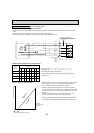
63HS
High pressure sen-
sor
63L
Low pressure switch
SV2
Solenoid valve 2
LED
CN3S