


NOTE: DIAGRAMS & ILLUSTRATIONS ARE NOT TO SCALE.
9
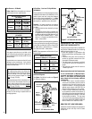
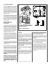
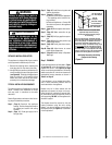
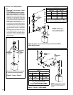
Left Side Front Corner of Fireplace Shown
(Right Side Requirements the Same)
Unit Being Secured By Its Nailing Flanges
To The Framing
Note: The nailing flanges, combustible members
and screw heads located in areas directly adjacent
to the nailing flanges, are EXEMPT from the 1/2”
clearance to combustible requirements for the
firebox outer wrapper. Combustible framing may be
in direct contact with the nailing flanges and may
be located closer than 1/2” from screw heads and
the firebox wrapper in areas adjacent to the nailing
flanges. Frame the opening to the exact dimensions
specified in the framing details of this manual.
Unit Being Secured by Its Nailing
Flanges to the Framing
Figure 11
Unit Being Secured by Its Nailing
Flanges to the Framing
Note: The nailing flanges
, combustible members
and screw heads locat
ed in areas directly ad
jacent
to the
nailing flanges, are
EXEMPT from the 1/2”
clearance to combusti
ble requirements for th
e
firebox outer wra
pper
. Combustible framing
may be
in
direct contact with
t
he nailing flanges and
m
ay
be loca
ted closer than 1/2” fr
om screw heads and
the firebox
wrapper in areas adjace
nt to the nailing
flanges. Frame th
e
opening to the exact dimens
ions
specified in the framing det
ails of this manual.
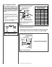
Use T
op Flange For
1/2” Thick Dr
ywal
l
Use Bottom Flange Fo
r
5/8” Thick Dr
ywal
l
Front Of
Fireplace
Use Center Flange
For Flush Mount
Left Side Front Co
rner of Fireplace Shown
(R
ight Side Requirements the
S
ame)
Unit Being Secured By Its Nailing Flanges
To The Framing
Step 3. (Page 12) Install the vent system and
exterior termination.
Step 4. (Page 21) Field Wiring
a. Millivolt and Electronic Appliances
– The operating control switch is fac-
tory installed.
b. Electronic Appliances – Connect 120
Vac electrical power to the appliance
receptacle.
Step 5. (Page 22) Remove glass door assem-
bly.
Step 6. (Page 22) Make connection to gas
supply.
Step 7. (Page 23) Verifying appliance opera-
tion.
Step 8. (Page 24) Install ceramic panels, logs
and glowing embers.
Step 9.
(Page 26) Install glass door assem-
bly.
Step 10.
(Page 26) Adjust burner to ensure
proper flame appearance.
Step 11. (Page 29) Attach Safety in Operation
Warnings.
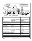
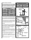
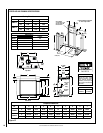
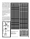
Step 1. FRAMING
Frame these appliances as illustrated in Figure
12 on Page 10, unless the appliance is to be
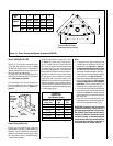
installed in a corner
. See Figure 13 on Page
11 for corner framing installations. All framing
details must allow for a minimum clearance to
combustible framing members as shown in
Table 5 on Page 8.
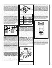
If the appliance is to be elevated above floor
level, a solid continuous platform must be
constructed below the appliance.
Headers may be in direct contact with the
appliance top spacers but must not be sup
-
ported by them or notched to fit around them.
All construction above the appliance must be
self-supporting,
DO NOT use the appliance for
structural support.
The fireplace should be secured to the side
framing members using the unit's nailing
flanges - one top and bottom on each side of
the fireplace front (see
Figure 11). Use 8d nails
or their equivalent.
DETAILED INSTALLATION STEPS
The appliance is shipped with all gas controls
and components installed and pre-wired.
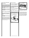
1. Remove the shipping carton, exposing the
front glass door on the valve access side.
2. Using a Phillips screwdriver, unfasten two (2)
screws located at the top of the glass frame
(see Figure 49). Tilt the top of the glass frame
away from the unit. Lift it carefully off the
bottom door track and set the door aside,
protecting it from inadvertent damage.
TYPICAL INSTALLATION SEQUENCE
The typical sequence of installation is outlined
below. However, each installation is unique
and may result in variations to the steps
described.
See the Page numbers references in the follow
-
ing steps for detailed procedures.
Step 1.
(Page 9) Construct the appliance
framing. Position the appliance within
the framing and secure with nailing
brackets.
Step 2.
(Page 11) Route gas supply line to
the right side.
WARNING
Failure to position the parts in
accordance with these diagrams
or failure to use only parts specifi-
cally approved with this appliance
may result in property damage or
personal injury.
AVERTISSEMENT
Risque de dommages ou de
blessures si les pièces ne sont
pas installées conformément à
ces schémas et ou si des pièces
autres que celles spécifiquement
approuvées avec cet appareil sont
utilisées.