


22
NOTE: DIAGRAMS & ILLUSTRATIONS ARE NOT TO SCALE.
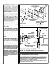
Step 5. REMOVE GLASS DOOR FRAME
Remove glass door assembly. See Removing
Glass Enclosure Panels on Page 26.
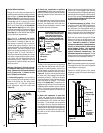
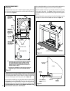
Step 6. CONNECTING GAS LINE
All codes require a shut-off valve mounted in
the supply line. The orientation of the shut-off
valve should face the front.
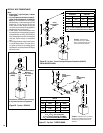
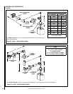
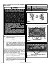
Figure 37 il-
lustrates two methods for connecting the gas
supply. A Sediment Trap is recommended to
prevent moisture and debris in gas line from
damaging the valve.
The flex-line method is acceptable in the U.S.A.
where local codes permit, however, Canadian
requirements vary depending on locality. Instal-
lation must be in compliance with local codes.
These appliances are equipped with a gas flex-
line for use in connecting the unit to the gas line.
See Figure 37 for flex-line description. The
flex-line is rated for both natural and propane
gas. A manual shut off valve is also provided
with the flex-line.
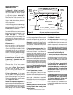
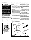
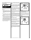
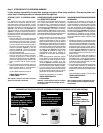
The gas control valve is located on the right
side of the unit.
When using solid gas line connector, access
the valve by removing the front door assembly
on the valve access side and the access plate
(refer to Figure 38).
The millivolt and electronic control valve has a
3/8" (10 mm) NPT thread gas supply inlet.
Bring the shutoff valve on the end of the flex-line
over to the hard pipe and tighten with wrenches
from above through the firebox opening.
Secure all joints tightly using appropriate
tools and sealing compounds (ensure propane
resistant compounds are used in propane ap-
plications). It is recommended to seal around
the gas line to prevent cold air leakage.
Piezo
Igniter
Gas Valve
ON/OFF Switch
Access Plate
Right Side
Modesty Panel
Hi-Lo
Extension Knob
Figure 38
Note: The gas supply line
must be installed in accor-
dance with building codes
by a qualified installer
approved and/or licensed
as required by the locality.
In the Commonwealth of
Massachusetts, installation
must be performed by a
licensed plumber or gas
fitter.
Gas
Valve
3/8" NPT x
Flare Fitting
3/8" Flex Tubing
3/8" Nipple
3/8" Union
3/8" Close
Nipple
3/8" Shut-off Valve
1/2" x 3/8"
Reducer
Gas
Stub
1/2" x 3/8" Flare
Shut-off Valve
Gas Solid Line Connector
Gas Flex Line Connector
*Sediment
Trap
3"
Min
Figure 37 - GAS CONNECTION
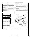
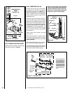
Figure 36- J-BOX WIRING
J-BOX/RECEPTIACLE
WIRING
120V, 60HZ, 1PH
Factory Wired
Field Wired
Junction Box
Tab Intact
Tab
Intact
n
e
e
r
G
-
d n
u
o
r
G
e
t i
h
W
-
l a r
t
u
e
N
120 VAC - Black
Green
Ground
Screw
White
Green
Neutral
Side of
Receptacle
Hot
Side of
Receptacle
Black