


8
NOTE: DIAGRAMS & ILLUSTRATIONS ARE NOT TO SCALE.
*Note: 3 in. (75 mm) above any horizontal/inclined vent component.
**Note: See Page 9, Step 1 for clearance requirements to the nailing
flange located at each side of the unit and any screw heads adjacent
to it.
The appliance should be mounted on a fully supported base extending
the full width and depth of the unit. The appliance may be located on
or near conventional construction materials. However, if installed on
combustible materials, such as carpeting, vinyl tile, etc., a metal or wood
barrier covering the entire bottom surface must be used.
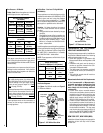
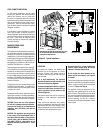
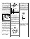
Shelf Height
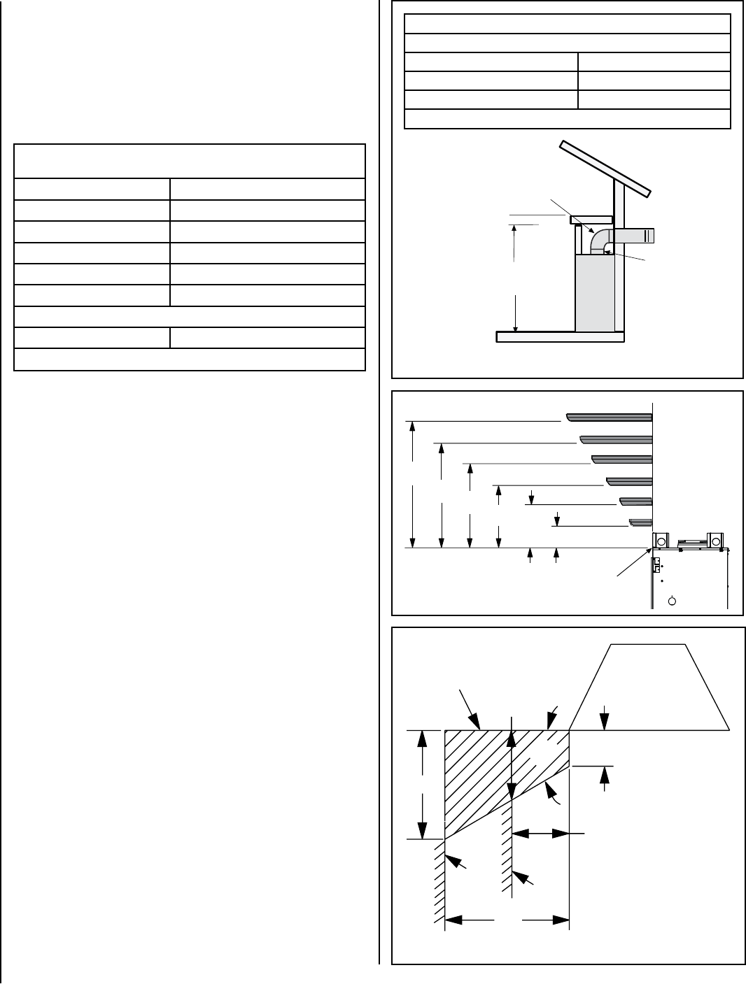
To provide for the lowest possible shelf surface, the venting attached to
the top vent should be routed in a way to minimize obstructions to the
space above the appliance. Do not insulate the space between the ap
-
pliance and the area above it (see
Figure 8). The minimum height from
the base of the appliance to the underside of combustible materials used
to construct a utility shelf in this fashion is shown in
Figure 8.
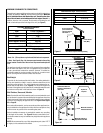
Wall Finishes / Surrounds / Mantels
Note: Combustible wall finish materials and/or surround materials must
not be allowed to encroach the area defined by the appliance front face
(black sheet metal). Never allow combustible materials to be positioned
in front of or overlapping the appliance face. See Figure 10 and Figure
53 on Page 28.
Non-combustible materials, such as surrounds and other appliance trim,
may be installed on the appliance front face with these exceptions: they
must not cover any portion of the removable glass panel.
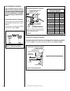
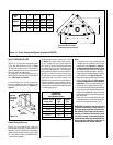
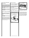
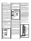
Vertical installation clearances to combustible mantels vary according
to the depth of the mantel. See
Figure 9. Mantels constructed of non-
combustible materials may be installed at any height above the appliance
opening.
NOTE: We recommend the use of high temperature paint (rated 175° F
or higher) on the underside of the mantel.
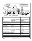
MINIMUM CLEARANCES TO COMBUSTIBLES
The appliance is approved with zero clearance to combustible materials on
all sides (as detailed in
Table 5), with the following exception: When the
unit is installed with one side flush with a wall, the wall on the other
side of the unit must not extend beyond the front edge of the unit. In
addition, when the unit is recessed, the side walls surrounding the unit
must not extend beyond the front edge of the unit (see
Figure 3).
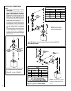
Figure 10
17"
14"
8-1/4”
45°
12"
5"
12 (305)
10 (254)
8 (203)
6 (152)
4 (102)
7
(178)
17
(432)
15
(381)
13
(330)
2 (51)
9
(229)
11
(279)
Figure 9
Combustible Materials
Allowed In Shaded Area
"Safe Zone"
Top View of
Fireplace
Minimum Distance to
Protected Side Wall
Minimum Distance to
Unprotected Side Wall
Side
Wall
Side
Wall
MANTEL
CLEARANCES
Inches (mm)
Top of Appliance
MANTEL
MANTEL
MANTEL
MANTEL
MANTEL
MANTEL
Fireplace
(side view)
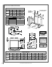
Figure 8
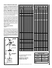
APPLIANCE MINIMUM CLEARANCES*
Inches (millimeters)
Sides 1/2 (13), 0 (0) Spacers **
Top Spacers 0 (0)
Floor 0 (0)
Back 1/2 (13), 0 (0) Spacers
Bottom of Appliance To Ceiling 69 (1743)
Vent 3 (76) Top* / 1 (25.4) Sides & Bottom
SERVICE CLEARANCES Feet (meters)
Front 3 feet (0.9 meters)
Table 5
Combustible Shelf Height - Inches (millimeters)
Top Vent - with 2 Feet Vertical Vent and One 90 Degree Elbow
Model Secure Vent
LSM40-2 *84-1/16 (2135)
LSM45-2 89-1/16 (2252)
* Includes 3” clearance to combustibles (required above vent components)
Do not insulate the
space between the
appliance and the
area above it.
2 Foot Vertical
Vent (Min.)
Shelf Height
(see table)
Shelf Above Fireplace With Top Venting