


NOTE: DIAGRAMS & ILLUSTRATIONS ARE NOT TO SCALE.
23
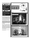
WARNING
Never use an open flame to
check for leaks.
Turn on gas supply and test for gas leaks using a
gas leak test solution (also referred to as bubble
leak solution).
Note:
Using a soapy water solution is an
effective leak test solution but it is not recom-
mended, because the soap residue that is left
on the pipes/fittings can result in corrosion
over time.
A. Light the appliance (refer to the lighting
instructions label in the control compartment
or in the Care and Operation Instructions
manual).
B. Brush all joints and connections with the gas
leak test solution to check for leaks. If bubbles
are formed, or gas odor is detected, turn the
gas control knob (off/pilot/on) to the “OFF”
position. Either tighten or refasten the leaking
connection, then retest as described above.
C. When the gas lines are tested and leak free be
sure to rinse off the leak testing solution.
D. Re-install the access plate, making certain the
gasket has not been damaged.
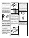
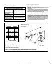
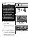
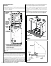
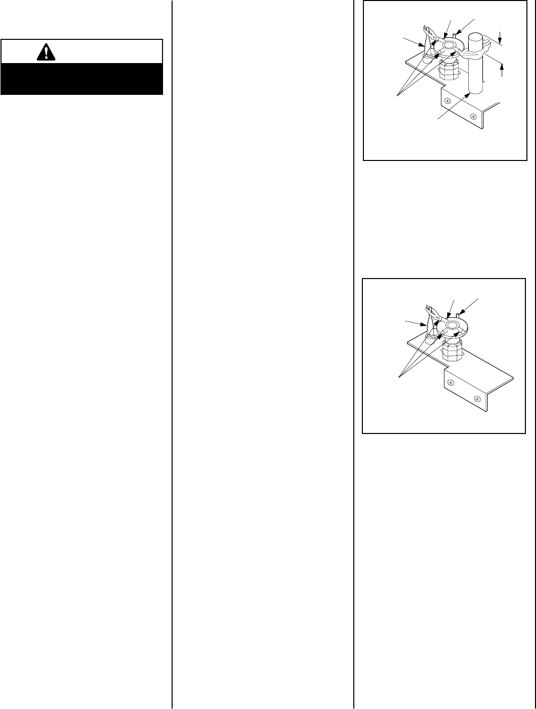
Figure 39
ELECTRONIC
Flame
Sensor
Hood
Ignitor Rod
Pilot
Nozzels
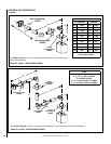
Figure 40
MILLIVOLT
Thermocouple
Hood
Igniter Rod
3/8" Min
(9 mm)
Thermopile
Pilot
Nozzels
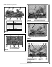
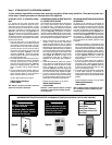
Step 7. CHECKING APPLIANCE OPERA-
TION
Turn on burner then observe the individual
tongues of flame on the burner. Make sure
all ports are open and producing flame evenly
across the burner. If any ports are blocked, or
partially blocked, clean out the ports.
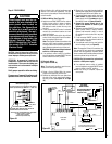
With gas line installed run initial system check
-
out before closing up the front of the unit.
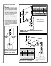
Follow the pilot lighting instructions provided.
For piezo igniter location refer to
Figure 38
(millivolt appliances only).
Note: Lighting Instructions are also found on
the literature tag tied to the bracket above the
gas valve. To access the tag, reach into the
right side opening.
When first lighting the appliance, it will take a few
minutes for the line to purge itself of air. Once
purging is complete, the pilot and burner will
light and operate as indicated in the instruction
manual. Subsequent lighting of the appliance
will not require such purging. Inspect the pilot
flame (remove logs, if necessary, handling
carefully).
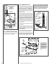
Millivolt Appliance Checkout
The pilot flame should be steady, not lifting
or floating. Flame should be blue in color with
traces of orange at the outer edge.
The top 3/8" (10 mm) at the pilot generator
(thermopile) and the top 1/8" minimum (tip)
of the quick drop out thermocouple should be
engulfed in the pilot flame.
The flame should project 1" (25 mm) beyond the
hood at all three ports (see
Figure 39). Replace
logs if removed for pilot inspection.
To light the burner; rotate the gas valve control
knob counterclockwise to the “ON” position
(“ON” will be at the bottom side of the valve)
and turn “ON” the appliance mounted ON/OFF
switch.
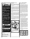
TEST ALL CONNECTIONS FOR GAS LEAKS
(FACTORY AND FIELD):
Electronic Appliance Checkout
To light the burner, turn ‘ON’ the optional remote
wall switch or turn the appliance mounted
ON/OFF switch to the “ON” position. Ensure
the igniter lights the pilot. The pilot flame
should engulf the flame sensor as shown in
Figure 40.