


NOTE: DIAGRAMS & ILLUSTRATIONS ARE NOT TO SCALE.
17
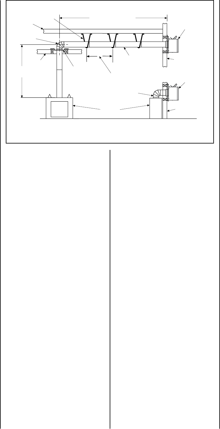
Vertical
Rise
SV8E90
Elbow
Horizontal / Inclined Run
SV8HTS
Termination
Shown
Firestop/Spacer
SV8 L6/12/24/36/48
Vent Sections
Support Bracket Spacing
Every 3 ft (914 mm)
SV8HTS
Termination
Shown
Support
Brackets
Building
Support
Framing
Ceiling
Fireplace
Exterior
Wall
Exterior
Wall
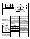
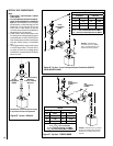
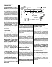
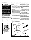
TYPICAL HORIZONTAL VENT INSTALLATION
2-1/2 Foot Vertical
Vent (min.)
Figure 28
Support the vertical portion of the venting system
every 8 feet (2.4m) above the fireplace vent outlet.
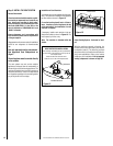
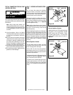
Push the vent component against the collar
until it fully engages, then twist the component
clockwise, running the dimples down and along
the incline channels until they seat at the end
of the channels. The unitized design of the
Secure Vent components will engage and seal
both the inner and outer pipe elements with the
same procedure. Sealant and securing screws
are not required.
E. Attach vent components to each other - Other
vent sections may be added to the previously
installed section in accordance with the require
-
ments of the vent tables. To add another vent
component to a length of vent run, align the
dimpled end of the component over the inclined
channel end of the previously installed section,
adjusting the radial alignment until the four lock
-
ing dimples are aligned with the inlets of the four
incline channels of the previous section. Push
the vent component against the previous section
until it fully engages, then twist the component
clockwise running the dimples down and along
the incline channels until they seat at the end of
the channels.
This seating position is indicated
by the alignment of the arrow and dimple as
shown in Figure 19 on Page 14.
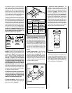
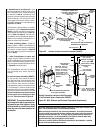
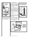
F. Install firestop/spacer at ceiling -
When using
Secure Vent, use SV8BF firestop/
spacer at ceiling joists. If there is living space
above the ceiling level, the firestop/ spacer must
be installed on the bottom side of the ceiling.
If attic space is above the ceiling, the firestop/
spacer must be installed on the top side of
the joist. Route the vent sections through the
framed opening and secure the firestop/spacer
with 8d nails or other appropriate fasteners at
each corner.
Remember to maintain 1" (25 mm) clearance
to combustibles, framing members, and attic
or ceiling insulation when running vertical
chimney sections.
G. Support the vertical run sections -
See
Section E on Page 14.
H. Change vent direction - At transition from or
to a horizontal/inclined run, install the SV8E45
and SV8E90 elbows in the same manner as the
straight vent sections. The elbows feature a twist
section to allow them to be routed about the
center axis of their initial collar section to align
with the required direction of the next vent run
element.
Twist elbow sections in a clockwise
direction only so as to avoid the possibility of
unlocking any of the previously connected vent
sections (see Figure 19 on Page 14).
I. Continue installation of horizontal/inclined
sections - Continue with the installation of the
straight vent sections in horizontal/inclined run
as described in
Step E. Install support straps
every 3 feet (1914 mm) along horizontal/inclined
vent runs using conventional plumber’s tape.
See
Figure 28, it is very important that the
horizontal/inclined run be maintained in a
straight (no dips) and recommended to be in
a slightly elevated plane, in a direction away
from the fireplace of 1/4" rise per foot (20 mm
per meter) which is ideal, though rise per foot
run ratios that are smaller are acceptable all the
way down to at or near level.
It is important to maintain the required clear-
ances to combustibles: 1" (25 mm) at all sides
for all vertical runs; and 3" (76 mm) at the top,
1" (25 mm) at sides, and 1" (25 mm) at the
bottom for all horizontal/inclined runs.
Use a carpenter’s level to measure from a
constant surface and adjust the support straps
as necessary.
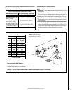
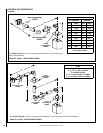
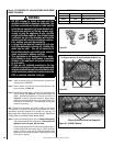
HORIZONTAL (OUTSIDE WALL)
TERMINATION SYSTEM
See
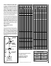
Figures 28, 31, 32 and 33 on Pages 17,
19 and 20 and their associated Horizontal Vent
Table which illustrate the various horizontal
venting configurations that are possible for
use with these appliances.
Secure Vent™
pipe applications are shown in these Figures.
A Horizontal Vent Table summarizes each
system’s minimum and maximum vertical and
horizontal length values that can be used to
design and install the vent components in a
variety of applications.
The horizontal vent system terminates through
an outside wall. Building Codes limit or prohibit
terminating in specific areas. Refer to
Figure 7
on Page 7 for location guidelines.
Secure Vent SV8 direct-vent system compo-
nents are unitized concentric pipe components
featuring positive twist lock connection, (
refer
to Figure 19 on Page 14). All of the appli-
ances covered in this document are fitted with
collars having locking inclined channels. The
dimpled end of the vent components fit over
the appliance collar to create the positive twist
lock connection.
A. Plan the vent run -
Analyze the vent routing and determine the
types and quantities of sections required
4-1/2" (114 mm), 10-1/2" (267 mm), 22-1/2"
(572 mm), 34-1/2" (876 mm) and 46-1/2" (1181
mm) net section lengths are available. It is
recommended that you plan the vent lengths
so that a joint does not occur at the intersection
of ceiling or roof joists. Make allowances for
elbows as indicated in
Figure 21 on Page 15.
Maintain a minimum 1" (25 mm) clearance
to combustibles on the vertical sections.
Clearances for the horizontal runs are; 3"
(76 mm) on top, 1" (25 mm) on sides, and
1" (25 mm) at the bottom.
B. Frame exterior wall opening -
Locate the center of the vent outlet on
the exterior wall according to the dimen
-
sions shown in
Figure 12 on Page 10.
Cut and/or frame an opening, 15" x 13"
(381 mm x 330 mm) inside dimensions, with
9" above center and 7" below center.
C. Frame ceiling opening - If the vertical
route is to penetrate a ceiling, use plumb line
to locate the center above the appliance. Cut
and/or frame an opening, 13" x 13" (330 mm x
330 mm) inside dimensions, about this center
(refer to
Figure 18 on Page 14).
D. Attach vent components to appliance - To
attach a vent component to the appliance collar,
align the dimpled end over the collar, adjust
-
ing the radial alignment until the four locking
dimples are aligned with the inlets of the four
incline channels on the collar (
refer to Figure
19 on Page 14).