


NOTE: DIAGRAMS & ILLUSTRATIONS ARE NOT TO SCALE.
19
H
V
Wall Firestop/Spacer
(SV8HF)
Ceiling
Firestop/Spa
ce
r
(SV8BF)
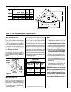
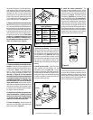
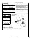
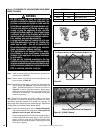
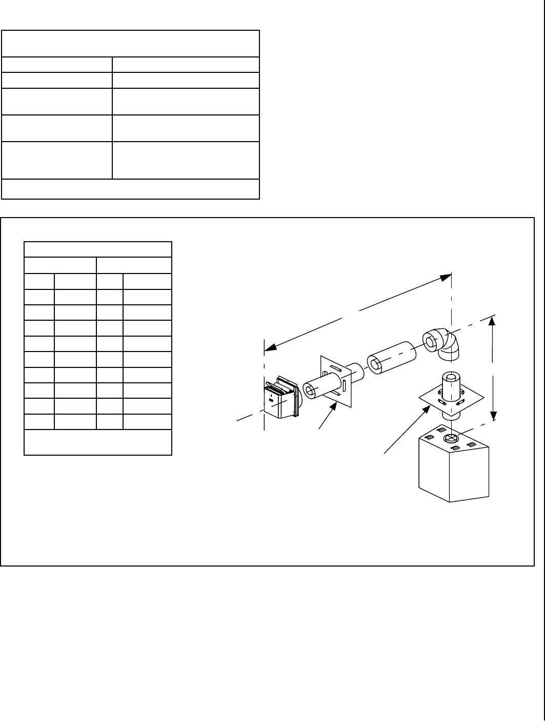
Table C
H Maximum
V Minimum
feet (meter) feet (meter)
3.5 (1.07) 2.5 (0.762)
6.5 (1.98) 3.5 (1.07)
8.5 (2.6) 4.5 (1.37)
10.5 (3.2) 5.5 (1.68)
12.5 (3.8) 6.5 (1.98)
14.5 (4.4) 7.5 (2.3)
16.5 (5.0) 8.5 (2.6)
18.5 (5.6) 9.5 (2.9)
20 (6.0) 10 (3.0)
V + H = 40 feet (12.4 m) Max.
H = 20 ft. (6.2 m) Max.
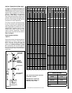
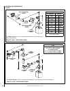
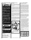
Venting Components Required for Various Exterior Wall Thick-
nesses, when using Square Termination Kit (SV8HTS)
Vent Components Required Exterior Wall Thickness - inches (mm)
Termination Kit Only 5 to 8-1/2 (127 to 216)
Termination Kit and 6 In. Vent
Section (SV8L6)
9-3/4 to 14 (248 to 356)
Termination Kit and Tele
-
scopic Section (SV8LA)
6-3/4 to 15-1/4 (171 to 387)
Termination Kit and Tele
-
scopic Section (SV8LA) and 6
in. vent section (SV8L6)
11-1/4 to 19-3/4 (286 to 502)
Table 8
See Table 8 as an aid in venting component selection for a particular
range of exterior wall thicknesses.
Example: If 20 feet of (H) hori-
zontal vent run is needed, then
10 feet minimum of (V) vertical
vent will be required.
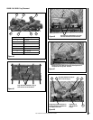
HORIZONTAL VENT FIGURES/TABLES
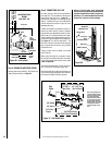
Notes:
• Secure Vent™
components (rigid vent pipe and terminal) are shown
in the Figures.
•
Two 45 degree elbows may be used in place of one 90 degree elbow.
The same rise to run ratios, as shown in the venting figures for 90
elbows, must be followed if 45 degree elbows are used.
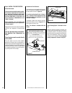
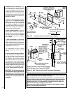
• SV8BF (Secure Vent) firestop/spacer must be used anytime vent pipe
passes through a combustible floor or ceiling. SV8HF (Secure Vent)
firestop/spacer must be used anytime vent pipe passes through a
combustible wall.
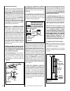
• It is very important that the horizontal/inclined run be maintained
in a straight (no dips) and recommended to be in a slightly elevated
plane, in a direction away from the fireplace of 1/4" rise per foot (20
mm per meter) which is ideal, though rise per foot run ratios that are
smaller are acceptable all the way down to at or near level.
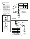
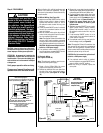
Figure 31 - Top Vent - ONE 90 DEGREE ELBOW - ELBOW CONNECTION NOT DIRECTLY AT APPLIANCE
See Table 8 as an aid in venting component selection for
a particular range of exterior wall thicknesses.
Square termination (SV8HTS) shown.