


10
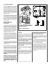
NOTE: DIAGRAMS & ILLUSTRATIONS ARE NOT TO SCALE.
E
A
B
D
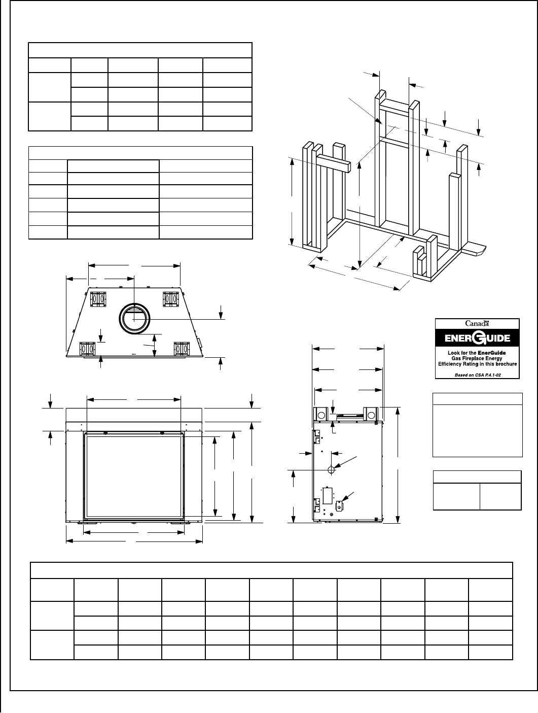
Top View
Front View
5-3/32 (129)
Right Side View
14-1/8
8-1/2”
(216)
5-1/4”
(133)
(359)
26-15/32
(672)
C
25-29/32
(658)
25-1/2
(648)
7
2-1/2 (64)
(178)
19-5/8
(498)
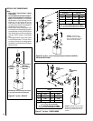
Gas Inlet
(This
Side
Only)
Electrical
Inlet
8-3/8
(213)
F
G
H
J
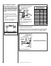
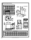
Fireplace Dimensions
Model
No.
A B C D E F G H J
LSM40-2
in. 50-5/8 37-1/4 42-7/8 25-5/16 34 37-5/8 33-3/32 29-9/32 34-3/4
mm 1286 946 1089 643 864 956 840 744 883
LSM45-2
in. 56-11/16 42-1/4 47-7/8 28-3/8 40-1/8 43-5/8 38-3/32 34-1/2 40-59/64
mm 1440 1073 1216 721 1019 1108 968 876 1039
Notes
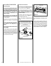
Diagrams, illustrations and photo-
graphs are not to scale – consult
installation instructions. Product
designs, materials, dimensions,
specifications, colors and prices are
subject to change or discontinuance
without notice.
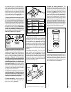
Vent Size
Co-axial DV
Vent Size
8" Inner
11" Outer
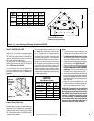
Figure 12
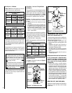
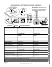
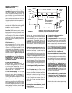
FIREPLACE AND FRAMING SPECIFICATIONS
Framing Dimensions
Models A B C
LSM40-2
in. 50-3/4 43 75-1/8
mm 1289 1092 1908
LSM45-2
in. 56-7/8 48 80-1/16
mm 1445 1219 2034
A
B
C
8-1/2
(216)
13
(
330
)
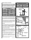
VENT FRAMING
-
TOP VENT WITH 2 FEET
VERTICAL VENT AND
ONE 90° ELBOW
Framing should be constructed
of 2x4 or larger lumber.
Inches (mm)
(641)
25-1/4
15
(
381
)
6-1/2
(165)
1/2 A
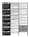
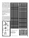
Efficiencies %
Natural Gas Propane
Models P4 P4
LSM40M 35% 38.1
LSM40E 35.8
LSM45M 50.8 42.3
LSM45E 51.2