


NOTE: DIAGRAMS & ILLUSTRATIONS ARE NOT TO SCALE.
13
T
ermination
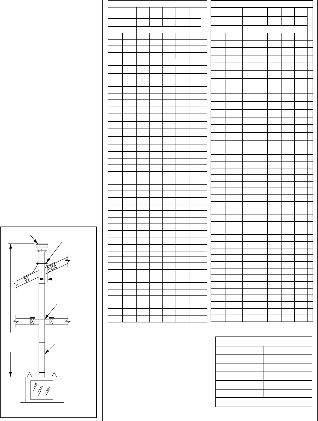
Flashing An
d
Storm Collar
Fires
top/Spacer
SV
8
6/12/24/36/48
V
ent Section
s
40' Ma
x
(12.2 M)
6' Mi
n
(1.8 M)
1" (25 mm
)
Minimum
Clearance to
Combustibles
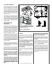
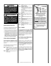
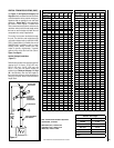
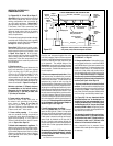
VERTICAL TERMINATION SYSTEMS (ROOF)
See
Figure 17 and Figures 25 through 27 on
Page 16 and their associated Vertical Vent Tables
which illustrate the various vertical venting con
-
figurations that are possible for use with these
appliances. Secure Vent™ pipe applications
are shown in these Figures. A Vertical Vent
Table summarizes each system’s minimum and
maximum vertical and horizontal length values
that can be used to design and install the vent
components in a variety of applications.
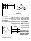
The vertical vent system terminates through
the roof. The minimum vent height above the
roof and/or adjacent walls is specified in ANSI
Z223.1-(latest edition) (In Canada, the current
CAN/CSA-B149.1 installation code) by major
building codes. Always consult your local
codes for specific requirements. A general
guide to follow is the Gas Vent Rule (refer to
Figure 5 on Page 6).
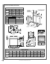
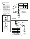
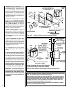
Vertical (Straight) Installation
(Figure 17)
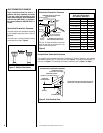
Determine the number of straight vent sections
required. 4-1/2" (114 mm), 10-1/2" (267 mm),
22-1/2" (572 mm), 34-1/2" (876 mm) and
46-1/2" (1181 mm) net section lengths are
available (see Tables on this page and Page
30 - Vent Sections). Plan the vent lengths so
that a joint does not occur at the intersection of
ceiling or roof joists. Refer to the Vent Section
Length Chart.
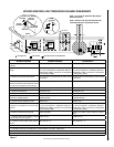
Note: Convert inches into metric equivalent
measurement, as follows:
Millimeters (mm) = Inches x 25.4
Centimeters (cm) = Inches x 2.54
Meters (M) = Inches x .0254
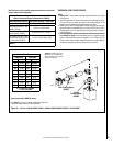
TRAHCHTGNELNOITCESTNEV
lanimoN
htgneLnoitceS
)sehcni(
6 21 42 63 84
T
O
T
A
L
Q
T
Y
noitceSteN
)sehcni(htgneL
2/1-4 2/1-01 2/1-22 2/1-43 2/1-64
tneVfothgieH snoitceStneVforebmuN
sehcni tf
5.4 573.0 1 0 0 0 0 1
9 57.0 2 0 0 0 0 2
5.01 578.0 0 1 0 0 0 1
51 52.1 1 1 0 0 0 2
5.91 526.1 2 1 0 0
0
3
12 57.1 0 2 0 0 0 2
5.22 578.1 0 0 1 0 0 1
5.52 521.2 1 2 0 0 0 3
5.13 526.2 0 3 0 0 0 3
5.43 578.2 0 0 0 1 0 1
5.73 521.3 1 1 1 0 0 3
5.34 526.3 0 2 1 0 0 3
54 57.3 0 0 2 0 0 2
5.64 578.3 0 0 0 0 1 1
5.94 521.4 1 0 2 0 0 3
15 52.4 1 0 0 0 1 2
5.55 526.4 0 1 2 0 0 3
75 57.4 0 0 1 1 0 2
66 52.5 0 2 2 0 0 4
5.76 526.5 0 0 3 0 0 3
96 57.5 0 0 0 2 0 2
27 6 1 0 3 0 0 4
5.37 521.6 1 0 0 2 0 3
5.97 526.6 0 1 0 2 0 3
18 57.6 0 0 0 1 1 2
09 5.7 0 2 1 0 1 4
5.19 526.7 0 0 2 0 1 3
39 57.7 0 0 0 0 2 2
69 8 1 0 1 2 0 4
5.79 521.8 1 0 0 0 2 3
201 5.8 2 0 0 0 2 4
5.301 526.8 0 0 0 3 0 3
801 9 1 0 0 3 0 4
411 5.9 0 2 0 0 2 4
711 57.9 1 0 5 0 0 6
5.811 578.9 1 1 0 3 0 5
621 5.01 0 0 1 3 0 4
5.031 578.01 1 0 1 3 0 5
531 52.11 0 0 6 0 0 6
831 5.11 0 0 0 4 0 4
5.931 526.11 0 0 0 0 3 3
5.241 578.11 1 0 0 4 0 5
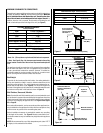
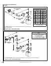
TRAHCHTGNELNOITCESTNEV
noitceSlanimoN
)sehcni(htgneL
6 21 42 63 84
T
O
T
A
L
Q
T
Y
noitceSteN
)sehcni(htgneL
2/1-4 2/1-01 2/1-22 2/1-43 2/1-64
tneVfothgieH snoitceStneVforebmuN
sehcni tf
441 21 1 0 0 0 3 4
051 5.21 0 1 0 0 3 4
5.451 578.21 1 1 0 0 3 5
5.061 573.31 0 2 0 0 3 5
5.271 573.41 0 0 0 5 0 5
771 57.41 1 0 0 5 0 6
381 52.51 0 1 0 5 0 6
681 5.51 0 0 0 0 4 4
5.091 578.51 1 0 0 0 4 5
5.691 573.61 0 1 0 0 4 5
5.502 521.71 0 1 1 5 0 7
702 52.71 0 0 0 6 0 6
5.112 526.71 1 0 0 6 0 7
5.712 521.81 0 1 0 6 0 7
5.922 521.91 0 0 1 6 0 7
5.232 573.91 0 0 0 0 5 5
732 57.91 1 0 0 0 5 6
5.142 521.02 0 0 0 7 0 7
642 5.02 1 0 0 7 0 8
252 12 0 1 0 7 0 8
462 22 0 0 1 7 0 8
672 32 0 0 0 8 0 8
972 52.32 0 0 0 0 6 6
5.082 573.32 1 0 0 8 0 9
5.382 526.32 1 0 0 0 6 7
5.982 521.42 0 1 0 0 6 7
5.103 521.52 0 0 1 0 6 7
5.013 578.52 0 0 0 9 0 9
513 5.62 1 0 0 9 0 01
5.523 521.72 0 0 0 0 7 7
033 5.72 1 0 0 0 7 8
633 82 0 1 0 0 7 8
543 57.82 0 0 0 01 0 01
5.943 521.92 1 0 0 01 0 11
273 13 0 0 0 0 8 8
5.673 573.13 1 0 0 0 8 9
5.973 526.13 0 0 0 11 0 11
5.814 578.43 0 0 0 0 9 9
324 52.53 1 0 0 0 9 01
564 57.83 0 0 0 0 01 01
Effective Vent Length
Model Effective Length
SV4.5L6 4-1/2"
SV4.5L12 10-1/2"
SV4.5L24 22-1/2"
SV4.5L36 34-1/2"
SV4.5L48 46-1/2"
Table 7
Figure 17