


10 Installation (for qualified installers only)
Travis Industries 100-01159 4040621
Gas Line Installation
! The gas line must be installed in accordance with all local codes, if any; if not, follow current ANSI
Z223.1 or NFPA 54 in the USA and the current CGA B149 in Canada.
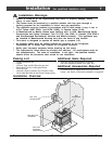
! The heater and gas control valve must be disconnected from the gas supply piping during any
pressure testing of that system at test pressures in excess of 1/2 psig (3.45 kPA). For pressures
under 1/2 psig (3.45 kPA), isolate the gas supply piping by closing the manual shutoff valve.
• This heater is designed for natural gas but can be converted to propane. Check the sticker on
top of the gas control valve to verify the correct fuel is used (see page 4).
• Leak test all gas line joints and the gas control valve prior to and after starting the heater.
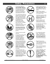
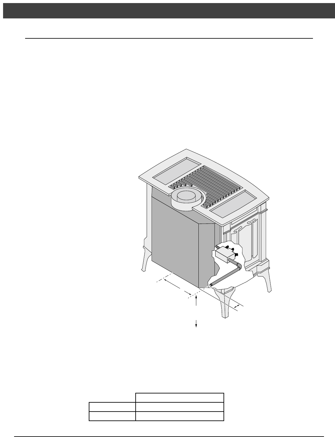
• The gas inlet accepts a 3/8” F.P.T. Fitting
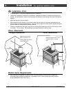
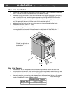
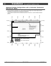
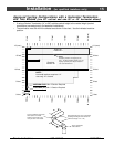
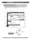
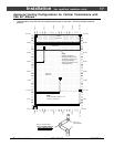
• The location of the gas inlet is shown below
• A manual shutoff valve is required for installation (it must be located within 3’ of the heater).
T-Handle gas cocks are required in Massachusetts in compliance with code 248CMR.
1-3/8"
8-3/4"
9-3/4"
Centerline
With the included pipe
installed, the gas inlet is
located at the location
shown below.
Gas Inlet Pressure
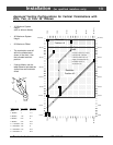
• With the heater off, the inlet pressure must meet the requirements listed in the table below
• If the pressure is not sufficient, make sure the piping used is large enough and the total gas load
for the residence does not exceed the amount supplied.
• The supply regulator (the regulator that attaches directly to the residence inlet or to the propane
tank) should supply gas at the suggested input pressure listed below. Contact the local gas
supplier if the regulator is at an improper pressure.
Standard Input Pressure
Natural Gas 7” W.C. (1.74 Kpa)
Propane 13” W.C. (3.23 Kpa)