


Introduction
6
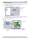
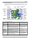
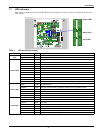
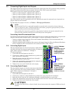
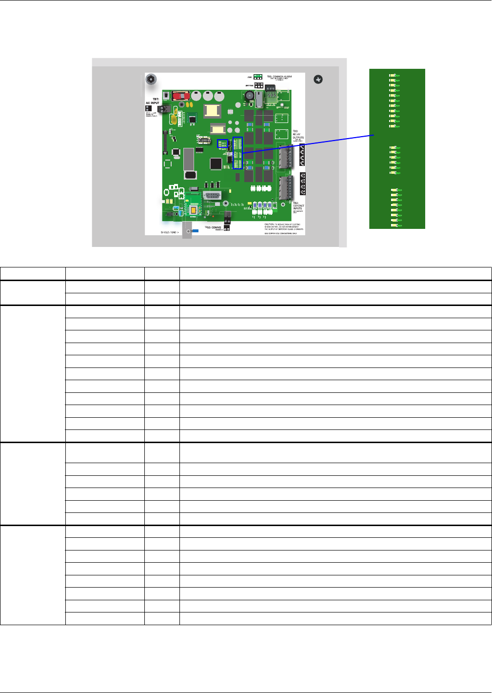
1.7 LED Indicators
The AC4’s controller board has LED indicators that show the status of inputs, outputs and the com-
mon alarm
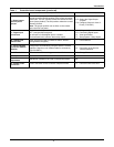
Table 2 LED indicators summary
LED Type LED Color Description
EIA422
LEDs
422 TX Green AC4 is transmitting information over the EIA422 port
422 RX Green AC4 is receiving information over the EIA422 port
Output LEDs
OUTPUT1 Green Not used
OUTPUT2 Green Not used
OUTPUT3 Green Not used
OUTPUT4 Green Not used
OUTPUT5 Green Indicates output 1 is ON or energized
OUTPUT6 Green Indicates output 2 is ON or energized
OUTPUT7 Green Indicates output 3 is ON or energized
OUTPUT8 Green Indicates output 4 is ON or energized
CTRLLOCK N/A Not used
SENLOCK N/A Not used
CMN ALR Green Indicates output is ON or energized
Status LEDs
MOP Green
Indicates the microprocessor is operating properly (MOP)—must be on before
AC4 will function
FPROG Green Indicates firmware is being upgraded—lights up during upgrade process
574 TX or 232 TX Green AC4 is transmitting information via the RS232 port
574 RX or 232 RX Green AC4 is receiving information via the RS232 port
485 RX Green Not used
485 TX Green Not used
Input LEDs
INPUT1 Red Not used
INPUT2 Red Not used
INPUT3 Red Not used
INPUT4 Red Not used
INPUT5 Red Indicates input 1 is ON or energized
INPUT6 Red Indicates input 2 is ON or energized
INPUT7 Red Indicates input 3 is ON or energized
INPUT8 Red Indicates input 4 is ON or energized
OUTPUT1
DS56
DS54
DS63
DS61
DS60
DS62
DS55
DS57
DS59
DS58
DS53
DS52
MOP
F PROG
574 TX
574 RX
485 RX
485 TX
DS51
DS48
DS47
DS78
DS79
OUTPUT2
OUTPUT3
OUTPUT4
OUTPUT5
OUTPUT6
OUTPUT7
OUTPUT8
CTRLLOCK
SENLOCK
CMN ALR
INPUT1
DS69
DS71
DS72
DS70
DS67
DS66
DS65
DS64
INPUT2
INPUT3
INPUT4
INPUT5
INPUT6
INPUT7
INPUT8
Output LEDs
Status LEDs
Input LEDs