


Introduction
4
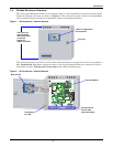
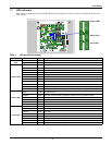
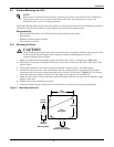
1.6 Controller Board Overview
The AC4’s controller board has connectors for four digital inputs and four digital outputs, as shown
below. The board comes complete with light emitting diodes (LEDs) to display the status of connected
devices, a serial communications port, a power connection and other features necessary to control
your operation.
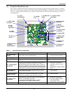
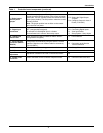
Table 1 Controller board components
Item Description For more information, see:
A - Power On/Off
switch
Power switch for the controller board. 2.4: Connect Power to the AC4
B - Audible horn Provides audible notification when an alarm occurs. N/A
C - Audible horn
jumper
Jumper to disable the audible horn (factory default is
enabled).
N/A
D - Common Alarm
connectors
The two common alarm connections are used to connect to
a secondary warning device such as a horn, light or
Building Management System (BMS). When an alarm is
present, the contacts close and the external warning device
is activated/notified. The common alarm contacts may be
configured to be reset with the Silence button/command.
3.0: Wiring and Connections
3.3: Connecting Common Alarm
Outputs
7.4: Setup System - Setup Common
Alarm
E - Digital output
status LEDs
Each output has an LED to indicate its status: ON/OFF
(energized/de-energized).
1.7: LED Indicators
F - Manual Override
Switch (outputs)
Placing the switch in the ON position will turn ON, or
energize, all four outputs simultaneously. This switch
removes all automatic output control from the AC4.
7.9: Override Output
G - Digital output
connectors
Each of the four output connections is a two-state point:
ON/OFF (energized/de-energized).
An example of a field digital output is a Liebert
Environmental unit’s remote shutdown input.
3.0: Wiring and Connections
3.2.2: Connecting Digital Outputs
5.5: View Output Status
7.6: Setup System - Setup Outputs
H - Status LEDs Indicates the operational status of the controller board. 1.7: LED Indicators
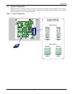
G - Digital output
connectors
J - Digital input
connectors
P - 24VAC power
connector
E - Digital output
status LEDs
I - Digital output
loss-of-power
jumper
F - Manual
Override Switch
(outputs)
H - Status LEDs
A - Power
On/Off switch
N - LCD
connector
K - Digital input
status LEDs
O - LCD
contrast
adjustment
M - DIP
switch 1
D - Common Alarm
connectors
C - Audible horn
jumper
B - Audible
horn
L - Serial interface
connector
(RS232/EIA574)